


App. 4-23
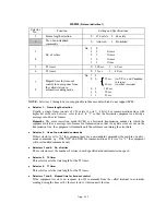
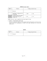
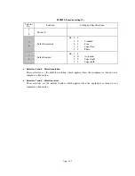
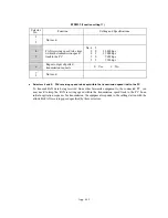
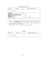
WSW20
(Overseas communications mode setting)
Selector
No.
Function
Setting and Specifications
1
EP* tone prefix
0: OFF
1: ON
2
Overseas communications
mode (Reception)
0: 2100 Hz
1: 1100 Hz
3
Overseas communications
mode (Transmission)
0: OFF
1: Ignores DIS once.
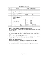
4
5
Min. time length from
reception of CFR to start of
transmission of video signals
No. 4
5
0
0 :
100
ms
0
1 :
200
ms
1
0 :
300
ms
1
1 :
400
ms
6
7
Not used.
8
CNG detection on/off
0: OFF
1: ON
* EP: Echo protection
Selector 1:
EP tone prefix
Setting this selector to "1" makes the equipment transmit a 1700 Hz echo protection (EP) tone
immediately preceding training in V.29 modulation system to prevent omission of training signals.
Prefixing an EP tone is effective when the equipment fails to transmit at the V.29 modem speed
and always has to fall back to 4800 bps transmission.
Selectors 2 and 3: Overseas communications mode
These selectors should be used if the facsimile equipment malfunctions in overseas
communications. According to the communications error state, select the signal specifications.
Setting selector 2 to "1" allows the equipment to use 1100 Hz CED signal instead of 2100 Hz in
receiving operation. This prevents malfunctions resulting from echoes, since the 1100 Hz signal
does not disable the echo suppressor (ES) while the 2100 Hz signal does.
Setting selector 3 to "1" allows the equipment to ignore a DIS signal sent from the called station
once in sending operation. This operation suppresses echoes since the first DIS signal immediately
follows a 2100 Hz CED (which disables the ES) so that it is likely to be affected by echoes in the
disabled ES state. However, such a disabled ES state will be removed soon so that the second and
the following DIS signals are not susceptible to data distortion due to echoes. Note that some
models when called may cause error by receiving a self-outputted DIS.
Selectors 8: CNG detection on/off
If this selector is set to "1," the equipment detects a CNG signal according to the condition preset
by selectors 2 and 3 of WSW18 after a line is connected. If it is set to "0," the equipment detects a
CNG signal as long as the line is connected.
Содержание MFC-5200C
Страница 1: ...FACSIMILE EQUIPMENT SERVICE MANUAL MODEL MFC5200C MFC890 ...
Страница 7: ...CHAPTER 1 PARTS NAMES FUNCTIONS ...
Страница 8: ...CHAPTER 1 PARTS NAMES FUNCTIONS CONTENTS 1 1 EQUIPMENT OUTLINE 1 1 1 2 CONTROL PANEL 1 3 ...
Страница 13: ...CHAPTER 2 SPECIFICATIONS ...
Страница 18: ...2 4 2 1 4 Environmental Condition ...
Страница 23: ...CHAPTER 3 INSTALLATION ...
Страница 26: ...3 2 3 2 UNPACKING THE MACHINE The equipment consists of the following major components ...
Страница 34: ...CHAPTER 4 THEORY OF OPERATION ...
Страница 54: ...CHAPTER 5 MAINTENANCE ...
Страница 60: ...CHAPTER 6 DISASSEMBLY REASSEMBLY LUBRICATION AND ADJUSTMENT ...
Страница 141: ...6 79 2 Separation roller and document feed roller 3 Document ejection roller ...
Страница 146: ...6 84 11 Purge shaft EM4 Main chassis ...
Страница 147: ...6 85 12 Carriage Viewed from the rear After lubrication more this to the right and left Carriage EM2 EM4 EM4 EM3 EM3 ...
Страница 151: ...CHAPTER 7 MAINTENANCE MODE ...
Страница 160: ...7 8 Scanning Compensation Data List ...
Страница 174: ...7 22 Vertical Alignment Check Pattern ...
Страница 176: ...7 24 Paper Feeding Check Patterns for the Paper Feed Roller and Paper Ejection Roller Pattern A Pattern B ...
Страница 183: ...CHAPTER 8 ERROR INDICATION AND TROUBLESHOOTING ...
Страница 213: ...8 29 4 Close the manual feed cover ...
Страница 214: ...MFC5200C MFC890 Appendix 1 Serial No Descriptions ...
Страница 215: ...SERIAL NO DESCRIPTIONS The descriptions as below shows how to read labels on each place 1 SET Location ...
Страница 216: ... 2 PRINTER HEAD UNIT Location ...
Страница 228: ...MFC5200C MFC890 Appendix 3 EEPROM Customizing Codes ...
Страница 231: ...MFC5200C MFC890 Appendix 4 Firmware Switches WSW ...
Страница 274: ...MFC5200C MFC890 Appendix 5 Re Packing Instructions ...
Страница 276: ... 8 Place the machine in the original box with the original packaging material ...
Страница 277: ...MFC5200C MFC890 Appendix 6 Wiring Diagram ...
Страница 280: ...A Main PCB 1 4 MFC5200C ...
Страница 281: ...A Main PCB 2 4 MFC5200C ...
Страница 282: ...A Main PCB 3 4 MFC5200C ...
Страница 283: ...A Main PCB 4 4 MFC5200C ...
Страница 284: ...B Driver PCB 1 2 ...
Страница 285: ...B Driver PCB 2 2 ...
Страница 286: ...C NCU PCB MFC5200C ...
Страница 287: ...D Control Panel PCB 1 2 MFC5200C ...
Страница 288: ...D Control Panel PCB 1 2 MFC890 ...
Страница 289: ...D Control Panel PCB 2 2 ...
Страница 290: ...E Power Supply PCB MFC5200C ...
Страница 291: ...F Carriage PCB ...
Страница 292: ...G Media PCB 1 2 ...
Страница 293: ...G Media PCB 2 2 ...
Страница 294: ...Aug 02 SM FAX013 1 8CA503 Printed in Japan ...


