


6-60
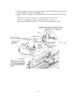
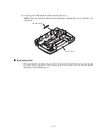
(12) Remove the FFC stopper 1 from the rear side of the print head unit in the order of and as
shown below.
(13) Disconnect the head flat cable W (driver-head signal line) towards the rear.
(14) Unlock the connector of the head flat cable M (main-head power line) and disconnect it
upwards.
Latch
Printed sides
Head flat cable W
(driver-head signal line)
Head flat cable M
(main-head power line)
Latch
FFC stopper 1
Head flat cable M
(main-head power line)
Head flat cable W
(driver-head signal line)
Print head unit
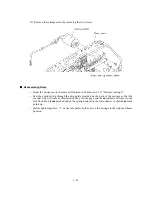
NOTE:
Do not touch the printing ends (nozzles) of the print head unit or the ink orifices of the
ink cartridges; doing so will not only stain your hands with ink but result in an ink jet-out
failure. Once you touch them, clean them with a dedicated cleaning stick and liquid.
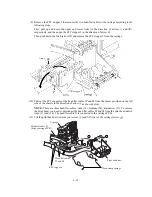
NOTE:
Be sure to put a head nozzle seal and filter seal on the print head unit as shown below.
Leaving the print head unit without those seals will dry up its printing ends and filters,
resulting in a damaged head.
Head filter seal
Print head unit
Head nozzle seal
Содержание MFC-5200C
Страница 1: ...FACSIMILE EQUIPMENT SERVICE MANUAL MODEL MFC5200C MFC890 ...
Страница 7: ...CHAPTER 1 PARTS NAMES FUNCTIONS ...
Страница 8: ...CHAPTER 1 PARTS NAMES FUNCTIONS CONTENTS 1 1 EQUIPMENT OUTLINE 1 1 1 2 CONTROL PANEL 1 3 ...
Страница 13: ...CHAPTER 2 SPECIFICATIONS ...
Страница 18: ...2 4 2 1 4 Environmental Condition ...
Страница 23: ...CHAPTER 3 INSTALLATION ...
Страница 26: ...3 2 3 2 UNPACKING THE MACHINE The equipment consists of the following major components ...
Страница 34: ...CHAPTER 4 THEORY OF OPERATION ...
Страница 54: ...CHAPTER 5 MAINTENANCE ...
Страница 60: ...CHAPTER 6 DISASSEMBLY REASSEMBLY LUBRICATION AND ADJUSTMENT ...
Страница 141: ...6 79 2 Separation roller and document feed roller 3 Document ejection roller ...
Страница 146: ...6 84 11 Purge shaft EM4 Main chassis ...
Страница 147: ...6 85 12 Carriage Viewed from the rear After lubrication more this to the right and left Carriage EM2 EM4 EM4 EM3 EM3 ...
Страница 151: ...CHAPTER 7 MAINTENANCE MODE ...
Страница 160: ...7 8 Scanning Compensation Data List ...
Страница 174: ...7 22 Vertical Alignment Check Pattern ...
Страница 176: ...7 24 Paper Feeding Check Patterns for the Paper Feed Roller and Paper Ejection Roller Pattern A Pattern B ...
Страница 183: ...CHAPTER 8 ERROR INDICATION AND TROUBLESHOOTING ...
Страница 213: ...8 29 4 Close the manual feed cover ...
Страница 214: ...MFC5200C MFC890 Appendix 1 Serial No Descriptions ...
Страница 215: ...SERIAL NO DESCRIPTIONS The descriptions as below shows how to read labels on each place 1 SET Location ...
Страница 216: ... 2 PRINTER HEAD UNIT Location ...
Страница 228: ...MFC5200C MFC890 Appendix 3 EEPROM Customizing Codes ...
Страница 231: ...MFC5200C MFC890 Appendix 4 Firmware Switches WSW ...
Страница 274: ...MFC5200C MFC890 Appendix 5 Re Packing Instructions ...
Страница 276: ... 8 Place the machine in the original box with the original packaging material ...
Страница 277: ...MFC5200C MFC890 Appendix 6 Wiring Diagram ...
Страница 280: ...A Main PCB 1 4 MFC5200C ...
Страница 281: ...A Main PCB 2 4 MFC5200C ...
Страница 282: ...A Main PCB 3 4 MFC5200C ...
Страница 283: ...A Main PCB 4 4 MFC5200C ...
Страница 284: ...B Driver PCB 1 2 ...
Страница 285: ...B Driver PCB 2 2 ...
Страница 286: ...C NCU PCB MFC5200C ...
Страница 287: ...D Control Panel PCB 1 2 MFC5200C ...
Страница 288: ...D Control Panel PCB 1 2 MFC890 ...
Страница 289: ...D Control Panel PCB 2 2 ...
Страница 290: ...E Power Supply PCB MFC5200C ...
Страница 291: ...F Carriage PCB ...
Страница 292: ...G Media PCB 1 2 ...
Страница 293: ...G Media PCB 2 2 ...
Страница 294: ...Aug 02 SM FAX013 1 8CA503 Printed in Japan ...


