background image

vi

Brocade FastIron X Series Chassis Hardware Installation Guide

53-1001723-02

Replacing a management module. . . . . . . . . . . . . . . . . . . . . . . . . .118

Installation precautions. . . . . . . . . . . . . . . . . . . . . . . . . . . . . . .118
Removing a management module . . . . . . . . . . . . . . . . . . . . . .118
Installing a new management module . . . . . . . . . . . . . . . . . . .119

Replacing a switch fabric module (

FSX 800

 and 

FSX 1600

 only) .121

Removing a switch fabric module. . . . . . . . . . . . . . . . . . . . . . .122
Installing a new switch fabric module  . . . . . . . . . . . . . . . . . . .122

Replacing an interface module  . . . . . . . . . . . . . . . . . . . . . . . . . . . .124

Precautions  . . . . . . . . . . . . . . . . . . . . . . . . . . . . . . . . . . . . . . . .125
Before removing an interface module . . . . . . . . . . . . . . . . . . .125
Removing an interface module. . . . . . . . . . . . . . . . . . . . . . . . .126
Installing a new interface module. . . . . . . . . . . . . . . . . . . . . . .126
Configuring a LAN or WAN Phy interface module  . . . . . . . . . .129
Disabling and re-enabling an interface module. . . . . . . . . . . .130

Installing or replacing a POE daughter card . . . . . . . . . . . . . . . . . .131

Replacing a copper or fiber optic module . . . . . . . . . . . . . . . . . . . .134

Removing a copper or fiber optic module  . . . . . . . . . . . . . . . .134
Installing a new copper or fiber optic module . . . . . . . . . . . . .135
Cabling a fiber optic module . . . . . . . . . . . . . . . . . . . . . . . . . . .135

Installing or replacing a power supply . . . . . . . . . . . . . . . . . . . . . . .136

Determining which power supply failed . . . . . . . . . . . . . . . . . .136
Removing an AC power supply  . . . . . . . . . . . . . . . . . . . . . . . . .137
Removing a DC power supply . . . . . . . . . . . . . . . . . . . . . . . . . .139
Installing a new power supply . . . . . . . . . . . . . . . . . . . . . . . . . . 141
Connecting AC power to the chassis. . . . . . . . . . . . . . . . . . . . .145
Connecting DC power to the chassis  . . . . . . . . . . . . . . . . . . . . 147
Verifying proper operation . . . . . . . . . . . . . . . . . . . . . . . . . . . . .149
Displaying the status of the power supplies  . . . . . . . . . . . . . .151

Replacing the FSX and 

FSX 800

 fan tray. . . . . . . . . . . . . . . . . . . . .151

Replacing the 

FSX 1600

 fan assemblies  . . . . . . . . . . . . . . . . . . . .154

Replacing the 

FSX 1600

-ANR fan assemblies  . . . . . . . . . . . . . . . .155

Replacing the air filter in the FastIron SX-1600 . . . . . . . . . . . . . . .157

Upgrading the device to run Layer 3 software  . . . . . . . . . . . . . . . .158

Chapter 7

Hardware Specifications

Overview  . . . . . . . . . . . . . . . . . . . . . . . . . . . . . . . . . . . . . . . . . . . . . .159

Chassis specifications  . . . . . . . . . . . . . . . . . . . . . . . . . . . . . . . . . . .159

Physical dimensions  . . . . . . . . . . . . . . . . . . . . . . . . . . . . . . . . .159
Environmental considerations  . . . . . . . . . . . . . . . . . . . . . . . . .159
Cooling  . . . . . . . . . . . . . . . . . . . . . . . . . . . . . . . . . . . . . . . . . . . .160
Regulatory compliance  . . . . . . . . . . . . . . . . . . . . . . . . . . . . . . .163
Maximum power consumption . . . . . . . . . . . . . . . . . . . . . . . . .164
Power source interruptions . . . . . . . . . . . . . . . . . . . . . . . . . . . .165
Pinouts and signalling . . . . . . . . . . . . . . . . . . . . . . . . . . . . . . . .165
Cable specifications. . . . . . . . . . . . . . . . . . . . . . . . . . . . . . . . . .168
Power cords  . . . . . . . . . . . . . . . . . . . . . . . . . . . . . . . . . . . . . . . .169

Содержание FastIron SX 1600

Страница 1: ...53 1001723 02 18 March 10 Brocade FastIron X Series Chassis Hardware Installation Guide Supporting Release 07 0 01b ...

Страница 2: ...at accompany it The product described by this document may contain open source software covered by the GNU General Public License or other open source license agreements To find out which open source software is included in Brocade products view the licensing terms applicable to the open source software and obtain a copy of the programming source code please visit http www brocade com support oscd...

Страница 3: ...ii E mail access xii Telephone access xii Chapter 1 Product Overview Product overview 1 Hardware benefits 1 POE port density 2 Supported configurations 2 Software features 3 POE applications 3 Support for IPv6 modules 3 IPv6 hardware support guidelines 3 Hardware features 4 FSX chassis 4 FSX 800 chassis 7 FSX 1600 chassis 9 FSX 1600 ANR chassis 12 Management modules 14 Switch fabric modules FSX 80...

Страница 4: ...aching a PC or terminal to the console port or 10 100 1000 copper port 57 Attaching a switch to an Ethernet port 57 Powering on the system 58 Connecting AC power to the chassis 58 Connecting DC power to the chassis 60 Verifying proper operation 63 Observing the LEDs 64 Displaying the module status 66 Chapter 3 Connecting Network Devices and Checking Connectivity Overview 69 Assigning permanent pas...

Страница 5: ...verview 103 Management module switchover 104 Switchover implications 105 Management module redundancy configuration 106 Changing the default active chassis slot 106 Managing management module redundancy 107 File synchronization between the active and standby management modules 107 Manually switching over to the standby management module108 Rebooting the active and standby management modules 109 Hi...

Страница 6: ... Installing a new copper or fiber optic module 135 Cabling a fiber optic module 135 Installing or replacing a power supply 136 Determining which power supply failed 136 Removing an AC power supply 137 Removing a DC power supply 139 Installing a new power supply 141 Connecting AC power to the chassis 145 Connecting DC power to the chassis 147 Verifying proper operation 149 Displaying the status of ...

Страница 7: ...mpliance 174 Safety warnings 174 Appendix A Layer 3 Upgrade Procedures Overview 175 Upgrade kit contents 175 Installation overview 183 Detailed procedure 184 Hardware installation 184 Software installation 186 Appendix B Regulatory Statements U S A 189 Industry Canada statement 189 Europe and Australia 189 Japan VCCI statement 189 Japan Denan power cord statement 190 Korea 190 Russia 190 Appendix ...

Страница 8: ...viii Brocade FastIron X Series Chassis Hardware Installation Guide 53 1001723 02 ...

Страница 9: ...RIP OSPF BGP IGMP PIM DVMRP and VRRP Supported hardware and software The following hardware platforms are supported by this release of this guide FastIron SuperX FSX FastIron SX 800 FSX 800 FastIron SX 1600 FSX 1600 FastIron SX 1600 ANR FSX 1600 ANR Layer 2 or Layer 3 switches NOTE This document describes software release 07 0 01b only Refer to earlier releases of this guide for information about ...

Страница 10: ...d below in order of increasing severity of potential hazards NOTE A note provides a tip guidance or advice emphasizes important information or provides a reference to related information bold text Identifies command names Identifies the names of user manipulated GUI elements Identifies keywords Identifies text to enter at the GUI or CLI italic text Provides emphasis Identifies variables Identifies...

Страница 11: ...perties of their respective companies and corporations These references are made for informational purposes only Related publications The following Brocade documents supplement the information in this guide FastIron Configuration Guide Brocade FastIron Compact Switch Hardware Installation Guide IronWare MIB Reference NOTE For the latest edition of this document which contains the most up to date i...

Страница 12: ... errors To report errors click on Cases Create a New Ticket in the KP Make sure you specify the document title in the ticket description E mail access Send an e mail to IPsupport brocade com Telephone access United States and Canada 800 752 8061 International 800 AT FIBREE 800 28 34 27 33 Refer to the Services Support page on www brocade com for additional toll free numbers that may be available w...

Страница 13: ...odule is non blocking with a built in switch fabric module and twelve combination Gigabit Ethernet GbE copper or fiber ports that provide connectivity to your existing management network The FSX 800 and FSX 1600 management modules have a console port and a 10 100 1000 port that provide connectivity to your existing management network The management modules optionally support 2 port 10 GbE ports or...

Страница 14: ...o be premium devices Depending on the type of management module installed in the device IPv6 premium devices support either IPv4 multiprotocol routing and IPv6 host and management features or IPv6 and IPv4 multiprotocol routing and IPv6 host and management features For more information refer to FSX management modules on page 14 and FSX 800 and FSX 1600 management modules on page 18 All FastIron X ...

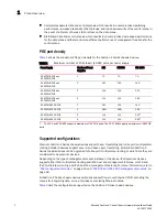
Страница 15: ...al outlet and dedicated UPS near IP powered devices With power sourcing devices such as Brocade s FastIron X Series chassis devices with POE power is consolidated and centralized in the wiring closets improving the reliability and resiliency of the network Because POE can provide power over Ethernet cable power is continuous even in the event of a power failure For POE port density refer to POE po...

Страница 16: ...gement modules which provide 100 redundancy Separate switch fabric modules FSX 800 and FSX 1600 only Interface modules Power supplies The fan tray in the FSX and FSX 800 is composed of six fans and a fan control module The FSX 1600 has an air filter in the bottom front of the chassis and two fan trays at the rear of the chassis Built in mounting brackets The following sections provide more informa...

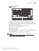
Страница 17: ...he chassis In the FSX slots you can install the following One management module Up to eight interface modules Up to four AC and DC power supplies two system 12 volt power supplies and two POE 48 or 220 volt power supplies Before installing any modules or power supplies you must remove the slot panel CAUTION If you do not install a module in a slot you must keep the slot panel in place If you run t...

Страница 18: ...ischarge ESD connector into which you can plug an ESD wrist strap to ground yourself while handling and installing modules DANGER For safety reasons the ESD wrist strap should contain a series 1 meg ohm resistor 1 Slot 1 2 Slot 2 3 Slot 3 4 Slot 4 5 Slot 5 6 Slot 6 7 Slot 7 8 Slot 8 9 Slot 9 10 ESD connector 11 Fan tray DC OK ALM AC OK SYS EJECT Odd Even Lnk Lnk Odd Even POE 424C 424F 8X 12GM 4 Co...

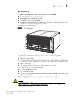
Страница 19: ...ing components installed Two switch fabric modules A slot panel in each interface module slot and power supply slot that does not currently have a module or power supply installed in it The slot panel ensures proper airflow within the chassis One AC power supply A fan tray assembly which contains the cooling system for the chassis In the FSX 800 slots you can install the following Up to two manage...

Страница 20: ...and installing modules DANGER For safety reasons the ESD wrist strap should contain a series 1 meg ohm resistor 1 Slot 1 2 Slot 2 3 Slot 3 4 Slot 4 5 Slot 5 6 Slot 6 7 Slot 7 8 Slot 8 9 Slot 9 10 Slot 10 11 Switch Fabric Slot 1 12 Switch Fabric Slot 2 13 Fan tray 14 ESD connector AC OK DC OK ALM EJECT SYS AC OK DC OK ALM EJECT SYS AC OK DC OK ALM EJECT POE AC OK DC OK ALM EJECT POE F1 424C F1 424C...

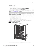
Страница 21: ...ssis on page 12 NOTE Except where explicitly noted throughout this manual the FSX 1600 and FSX 1600 ANR chassis are collectively referred to as the FSX 1600 chassis The FSX 1600 and FSX 1600 ANR chassis are 14 rack units in height and consist of the following Two half slots for the management modules Two half slots for the switch fabric modules Sixteen half slots for the interface modules Eight sl...

Страница 22: ...ich contains the cooling system for the chassis The FSX 1600 ANR chassis has an ANR kit attached to the rear of the chassis In the chassis slots you can install the following Up to two management modules Up to 16 interface modules Up to eight AC or DC power supplies four system SYS power supplies and four POE power supplies Before installing any modules or power supplies you must remove the slot p...

Страница 23: ...ou can install the various modules and power supplies FIGURE 6 FSX 1600 chassis slots 1 Interface slot 1 2 Interface slot 2 3 Interface slot 3 4 Interface slot 4 5 Interface slot 5 6 Interface slot 6 7 Interface slot 7 AC OK DC OK ALM EJECT SYS AC OK DC OK ALM EJECT SYS Pwr Active Pwr Active 1 3 5 7 9 11 19 13 15 17 21 12 20 14 16 18 2 4 6 8 10 ...

Страница 24: ... is an enhanced version of the FSX 1600 chassis Part numbers for the FSX 1600 ANR chassis and bundles begin with FI SX 1600 ANR xxx NOTE Except where explicitly noted throughout this manual the FSX 1600 and FSX 1600 ANR chassis are collectively referred to as the FSX 1600 chassis NOTE If you want to upgrade your existing FSX 1600 to an FSX 1600 ANR chassis you must ship it to Brocade where an ANR ...

Страница 25: ...hermal dissipation and reduced acoustic noise The front of the FSX 1600 ANR chassis is identical to the FSX 1600 and both chassis use the same switch fabric management and interface modules and power supplies Figure 7 shows the front of the chassis including a partial view of the ANR kit which is behind the chassis FIGURE 7 FSX 1600 ANR chassis front 1 ANR kit on rear of chassis 1 ...

Страница 26: ...d show version identify the chassis as an ANR chassis Also the SNMP object snChasType returns the chassis type ANR Chassis For details about the show chassis command refer to Overview on page 85 For details about the show version command refer to the section Viewing System Information in the FastIron Configuration Guide Management modules This section describes the management modules for the FastI...

Страница 27: ...h PREM provide additional support for full Layer 3 IPv4 routing protocols The IPv6 management modules ending with PREM6 provide additional support for full Layer 3 IPv4 and IPv6 routing protocols The FSX management module does the following Controls the FSX hardware components Houses and controls the switch fabric module Runs the networking protocols Provides the real time operating system The man...

Страница 28: ...ni GBIC slots for the types of fiber cabling listed in Table 32 on page 168 NOTE The Management Module does not support copper mini GBICs NOTE Some older SFP modules mini GBICs for Gigabit Ethernet ports have latching mechanisms which are larger than the newer parts These latches could interfere with one another when inserted side by side into a module Avoid using these mini GBICs side by side in ...

Страница 29: ... you can connect the Gigabit Ethernet ports must be separate and isolated from the network over which user packets are switched and routed as shown in Figure 10 FIGURE 10 Separate management and switching or routing networks LEDs on the FSX management module The FSX management module provides status information using the LEDs listed in Table 5 The location of the LEDs is as follows The fiber conne...

Страница 30: ...ement modules support full Layer 3 functionality NOTE The FSX 800 and FSX 1600 management modules are dedicated which means that you must install them in the FSX 800 or FSX 1600 chassis only If you attempt to install these management modules in the FSX or other Brocade chassis the chassis and modules will not function properly NOTE You cannot intermix different management modules in the same FSX 8...

Страница 31: ... fabric modules Run the networking protocols Provide the real time operating system FSX 800 management modules are located in slots 9 and 10 just above the switch module slots refer to Figure 4 FSX 1600 management modules are located in slots 9 and 10 along the center of the chassis refer to Figure 6 TABLE 6 FSX 800 and FSX 1600 management modules Part Number Description Microprocessor Speed MHz M...

Страница 32: ...lled in the device the management modules have the following ports no 10 GbE fiber ports two 10 GbE fiber ports eight GbE copper and fiber ports four copper and four fiber LEDs for power and active or standby status Four LEDs for the two 10 GbE fiber ports 2 port 10 GbE modules only A recessed reset button 10 100 1000 GbE Copper Port on the FSX 800 and FSX 1600 management modules The 10 100 1000 R...

Страница 33: ...s of fiber cabling listed in Table 32 on page 168 NOTE The Management Module does not support copper mini GBICs NOTE Some older SFP modules mini GBICs for Gigabit Ethernet ports have latching mechanisms which are larger than the newer parts These latches could interfere with one another when inserted side by side into a module Avoid using these mini GBICs side by side in the same module These olde...

Страница 34: ...tch fabric modules in the FSX 800 and FSX 1600 chassis are separate from the management modules and are physically located next to the management modules Figure 14 shows the FSX 800 and FSX 1600 switch fabric module FIGURE 14 FSX 800 and FSX 1600 switch fabric module Act Right most LED above the port On or Blinking The port is transmitting and receiving traffic Off The port is not transmitting or ...

Страница 35: ...supported Interface modules for each FastIron X Series chassis type TABLE 8 Switch fabric module LEDs LED Description and Position State Meaning Pwr Top most LED On Green The module is receiving power Off The module is not receiving power Active Bottom most LED On Green The module is functioning properly Off The module is not functioning properly TABLE 9 Interface modules Interface Module Part Num...

Страница 36: ...e module less than 10 seconds after the removal of a line module may result in the line module not being properly recognized Refer to Replacing an interface module on page 124 for instructions 24 port Gigabit Ethernet copper interface module The 24 port Gigabit Ethernet Copper interface module has 24 10 100 1000 ports with RJ 45 connectors for Cat5 cabling The copper ports support automatic MDI or...

Страница 37: ...ure 16 shows the front panel of the IPv6 24 port Gigabit Ethernet copper module FIGURE 16 IPv6 24 port Gigabit Ethernet copper module front panel The front panel includes the following control features 24 10 100 1000 copper ports 24 LEDs for port status 24 LEDs for Power over Ethernet POE status 1 Port 1 2 Port 2 13 Port 13 14 Port 14 24 Port 24 1 Port 1 2 Port 2 13 Port 13 14 Port 14 24 Port 24 4...

Страница 38: ...figure the highest performance mode of inter operation with the connected device The mini GBIC slots support the types of 1000Base fiber and copper cabling listed in Network interfaces on page 30 NOTE Some older SFP modules mini GBICs for Gigabit Ethernet ports have latching mechanisms which are larger than the newer parts These latches could interfere with one another when inserted side by side i...

Страница 39: ...ort 1 the second LED is for Port 2 and so on The ports provide status information using the LEDs described in Table 11 24 port 100 1000 hybrid fiber interface module The 100 1000 hybrid fiber module has 24 ports with connectors for mini GBIC transceivers also called Small Form Factor Pluggable SFP Multisource Agreement MSA compliant transceivers The ports support 100 and 1000 fiber mini GBICs 1 Po...

Страница 40: ...hybrid fiber interface module front panel The front panel includes the following control features 24 Gigabit Ethernet fiber ports 24 LEDs The ports on the 24 port 100 1000 Gigabit Ethernet Hybrid Fiber module operate at a fixed speed of 100 or 1000 Mbps they do not support 10 Mbps connections and use auto negotiation to automatically configure the highest performance mode of inter operation with t...

Страница 41: ...l ports through which you can connect the Brocade device to other network devices at a speed of 10 Gigabits per second The modules have two optical interfaces with LC connectors for 10 Gigabit Small Form Factor Pluggable XFP MSA compliant transceivers The transceivers support 10GBase SR 10GBase LR and 10GBase ER fiber optic cabling for LAN PHY or WAN PHY LAN or WAN module only Figure 20 shows the ...

Страница 42: ...ration of a feature it is noted and described in the appropriate feature section of this guide FSX Management Module Ports 1 12 FSX 800 and FSX 1600 Management Module with 2 port 10 GbE Port 1 Port 2 FSX 800 and FSX 1600 Management Module with 8 port GbE copper and fiber ports Ports 1 8 24 port Gigabit Ethernet Copper Interface Module TABLE 13 Network interfaces Interface Show Media Description 10...

Страница 43: ... volt AC power supplies for POE You can use any combination of the supported AC and DC supplies in the same device NOTE Note the following regarding POE power supplies The SX ACPWR2500 POE requires 220 volt input The SX ACPWR2500 POE powers up to 140 class 3 POE ports therefore the SX ACPWR POE is not sufficient as a backup power supply The following table lists the power supplies supported in the...

Страница 44: ...e if each POE power consuming device attached to the Brocade device consumes 15 4 watts of power one 48 volt supply will power up to 70 POE ports You can install a second 48 volt supply for additional POE power The 48 volt 220 volt input only POE power supplies provide power to the POE daughter card and ultimately to POE power consuming devices The number of POE power consuming devices that one 22...

Страница 45: ...r supplies occupy slot numbers 1 4 in the top row with the redundant supplies in slot numbers 3 and 4 The POE power supplies occupy slot numbers 5 8 in the bottom row Figure 23 shows power supply placement FIGURE 23 Power supply placement in the FSX 1600 The installed power supplies provide power to all chassis components sharing the workload equally If a power supply fails or overheats the failed...

Страница 46: ...er supply is being installed or removed but the power supply itself should not be connected to a power source Otherwise you could be injured or the power supply or other parts of the device could be damaged About replacement power supplies Replacement power supplies for the SX ACPWR SYS and SX ACPWR POE are functionally equivalent to the original power supplies and can be used in combination with ...

Страница 47: ... making the power supplies slightly longer in depth For the actual dimensions refer to Physical dimensions and weight on page 170 Although the model numbers SX ACPWR SYS and SX ACPWR POE for the replacement and original power supplies are identical the manufacturing part numbers are different as noted in Table on page 31 The manufacturing part numbers are inscribed on the labels affixed to the top...

Страница 48: ... Green steady The power supply is receiving DC power from a DC power source OFF The power supply is not receiving power from a DC power source You can do the following Make sure that the power supply cables are connected securely to the power source and the power supply Make sure that the DC power source is 48VDC 37 0 A Make sure that the power source has power DC OUT ON Green steady The power sup...

Страница 49: ...re capable of The system will react to a drop in voltage by increasing the current draw The hardware will shut down due to over current protection or under voltage protection whichever takes place first One by one the interface modules will shut down until the power is within the power budget of the remaining power supplies There is no particular order in which the interface modules will shut down...

Страница 50: ...t temperature polling interval refer to Changing the temperature polling interval on page 95 Depending on the temperature readings for the modules the system can do the following Leave the fan speed as is Increase the fan speed Decrease the fan speed If the chassis exceeds the highest temperature threshold or shutdown temperature for five minutes the system will shut down the device to prevent dam...

Страница 51: ...ing brackets and mounting the device in a rack The FSX 1600 does not have built in mounting brackets Two brackets ship with the FSX 1600 that enable you to front mount or center mount the chassis in a rack Contact Brocade for information about rack mount kits Layer 3 routing protocol table sizes Use the show default values command to display Layer 3 routing protocol table sizes The command output ...

Страница 52: ...40 Brocade FastIron X Series Chassis Hardware Installation Guide 53 1001723 02 Layer 3 routing protocol table sizes 1 ...

Страница 53: ...n configured on the device The CLI contains the following access levels User EXEC The level you enter when you first start a CLI session At this level you can view some system information but you cannot configure system or port parameters Privileged EXEC This level is also called the Enable level and can be secured by a password You can perform tasks such as manage files on the flash module save t...

Страница 54: ...Privileged level of the EXEC mode FastIron enable 2 Access the CONFIG level of the CLI by entering the following command FastIron configure terminal FastIron config 3 Enter the following command to set the super user password FastIron config enable super user password text NOTE You must set the super user password before you can set other types of passwords 4 Enter the following commands to set th...

Страница 55: ...prefix number for a network mask enter a forward slash and the number of bits in the mask immediately after the IP address For example enter 209 157 22 99 24 for an IP address that has a network mask with 24 significant mask bits By default the CLI displays network masks in classical IP address format example 255 255 255 0 You can change the display to the prefix format Refer to the FastIron Confi...

Страница 56: ...ntering the following command Privileged EXEC Level FastIron configure terminal Global CONFIG Level FastIron config 4 Configure the IPv4 address and mask address for the interface FastIron config int e 1 5 FastIron config if e1000 1 5 ip address 192 22 3 44 255 255 255 0 NOTE You can use the syntax ip address ip addr mask bits if you know the subnet mask length In the above example you could enter...

Страница 57: ...ave the running configuration to the startup config file 3 Access the configuration level of the CLI by entering the following command Privileged EXEC Level FastIron configure terminal Global CONFIG Level FastIron config 4 Configure the IPv4 address and mask for the switch FastIron config ip address 192 22 3 44 255 255 255 0 5 Set a default gateway address for the switch FastIron config ip default...

Страница 58: ... CAUTION Use the erase startup config command only for new systems If you enter this command on a system you have already configured the command erases the configuration If you accidentally do erase the configuration on a configured system enter the write memory command to save the running configuration to the startup config file 3 Access the configuration level of the CLI by entering the followin...

Страница 59: ...ase the configuration on a configured system enter the write memory command to save the running configuration to the startup config file 3 Access the configuration level of the CLI by entering the following command Privileged EXEC Level FastIron configure terminal Global CONFIG Level FastIron config 4 Configure the IP address and mask for the switch FastIron config ipv6 address 2001 200 12D 1300 2...

Страница 60: ...her Brocade devices Cable specifications Refer to Cable specifications on page 168 for cable lengths and types Connecting to Ethernet or fast Ethernet hubs For copper connections to Ethernet hubs a 10 100Base TX or 1000Base T switch or another Brocade device a crossover cable is required Figure 36 and Figure 37 If the hub is equipped with an uplink port it will require a straight through cable ins...

Страница 61: ...mation about this feature refer to the FastIron Configuration Guide FIGURE 36 UTP crossover cable FIGURE 37 Cat 5 crossover cable for 1000Base T NOTE The 802 3ab standard calls for automatic negotiation of the connection between two 1000Base T ports Consequently a crossover cable may not be required a straight through cable may work as well 1 1 2 2 3 3 6 6 4 5 7 1 1 2 2 3 3 6 8 4 4 5 7 8 1 8 UTP C...

Страница 62: ... or router fiber cabling with an LC connector is required NOTE All physical IP interfaces on FastIron X Series Layer 3 devices share the same MAC address For this reason if more than one connection is made between two devices one of which is a FastIron X Series Layer 3 device Brocade recommends the use of virtual interfaces It is not recommended to connect two or more physical IP interfaces betwee...

Страница 63: ...ctor located in the lower right corner of the chassis front 2 Remove the module from its protective packaging 3 If necessary remove the metal cover from the port on the interface module s control panel 4 Gently insert the fiber optic module into the port until the module clicks into place The fiber optic modules are keyed to prevent incorrect insertion Cabling a fiber optic module To cable a fiber...

Страница 64: ...r MDIX designate the port as an MDI port or designate the port as an MDIX port For more information about this feature and how configure it refer to the FastIron Configuration Guide Using a CX4 transceiver A twin axial 10G copper CX4 XFP transceiver can be installed in any 10G port For a link to operate properly both sides must use identical CX4 transceivers The CX4 transceiver requires a 15 meter...

Страница 65: ...tion and perform trace routes For more information about ping and traceroute commands refer to the FastIron Configuration Guide Observing LEDs After you install the network cables you can observe certain LEDs to determine if the network connections are functioning properly Table 19 outlines the LEDs related to the network connections the desired state of each LED possible abnormal states of each L...

Страница 66: ...ocade device is connected to the receive port on the other network device and that the receive port on the Brocade device is connected to the transmit port on the other network device If you are not certain remove the two cable connectors from the port connector and reinsert them in the port connector reversing their order Dust may have accumulated in the cable connector or port connector For info...

Страница 67: ... on the connected device For copper ports you can test the cable using Virtual Cable Testing For more information refer to the chapter Monitoring Hardware Components in the FastIron Configuration Guide If the other procedures do not resolve the problem try using a different port or a different cable Support for digital optical monitoring You can configure your Brocade device to monitor optical tra...

Страница 68: ...84 Brocade FastIron X Series Chassis Hardware Installation Guide 53 1001723 02 Troubleshooting network connections 3 ...

Страница 69: ...ks Task Number Task Where to Find More Information 1 Unpack the chassis and verify that all contents are present Unpacking a system on page 42 2 Review the installation cautions and warnings Installation precautions on page 43 3 Ensure that the physical environment that will host the chassis has proper cabling and ventilation Preparing the installation site on page 47 4 The FSX and FSX 800 chassis...

Страница 70: ... the regulations for power cords in your country The mark is your assurance that the power cord can be used safely with the device 6 The chassis ships with a slot panel installed in all module slots that do not currently have a module installed If you plan to install a module in a slot you must remove the slot panel CAUTION If you do not install a module in a slot you must keep the slot panel in p...

Страница 71: ...ces use Class 1 Lasers CAUTION Do not install the device in an environment where the operating ambient temperature might exceed 40 C 104 F CAUTION Make sure the air flow around the front sides and back of the device is not restricted CAUTION If you do not install a module in a slot you must keep the slot panel in place If you run the chassis with an uncovered slot the system will overheat CAUTION ...

Страница 72: ...d to prevent it from becoming unstable or falling over DANGER Mount the devices you install in a rack or cabinet as low as possible Place the heaviest device at the bottom and progressively place lighter devices above Power precautions and warnings DANGER The power supplies are hot swappable which means they can be removed and replaced while the chassis is powered on and running However Brocade re...

Страница 73: ...e system is one AC power supply DANGER Make sure that the power source circuits are properly grounded then use the power cord supplied with the device to connect it to the power source DANGER Disconnect the power cord from all power sources to completely remove power from the device CAUTION Do not install the device in an environment where the operating ambient temperature might exceed 40o C 104o ...

Страница 74: ...duces extensive power to support 802 3af applications Installing the power supply in a device other than the FastIron X Series POE will cause extensive damage to your equipment Use a separate branch circuit for each AC power cord which provides redundancy in case one of the circuits fails CAUTION Ensure that the device does not overload the power circuits wiring and over current protection To dete...

Страница 75: ... devices and equipment Allow at least 3 inches of space at the front of the device for the fiber optic and power cabling Also allow a minimum of 3 inches of space between the sides and the back of the device and walls or other obstructions Removing extra shipment screws FSX and FSX 800 only The FSX and FSX 800 ship with two extra screws installed in the right side of the chassis These screws secur...

Страница 76: ...brackets in the rack mount kit that ships with the chassis as shown in figure Figure 30 Before performing this task you should have an assembled rack and a 2 Phillips head screwdriver Keep the following in mind when mounting a chassis in a rack DANGER The Chassis devices are very heavy especially when fully populated with modules and power supplies TWO OR MORE PEOPLE ARE REQUIRED WHEN LIFTING HAND...

Страница 77: ...itioning two of four mounting screws in a rack 3 Start by mounting the chassis that goes in the lowest position in the rack as shown in Figure 29 With two or more people lifting the chassis slip the wide portion of each keyhole slot over the corresponding screw in the rack FIGURE 29 Mounting the FSX chassis in a rack front mount 4 Slide the chassis down so that the screw heads are in the narrow po...

Страница 78: ...GURE 30 Installing the mounting brackets on an FSX 1600 chassis Repeat step 3 through step 6 to install the FSX 1600 chassis in the rack Removing the slot panels The chassis ships with a slot panel installed that covers each empty module slot ensuring proper airflow within the chassis If you plan to install a module in a particular slot you must first remove the slot panel CAUTION If you do not in...

Страница 79: ... If you attempt to install the FSX management module in the FSX 800 FSX 1600 or other Brocade chassis the chassis and module will not function properly Likewise if you try to install the FSX 800 or FSX 1600 management module in the FSX or other Brocade chassis the chassis and module will not function properly NOTE The interface modules are interchangeable among all FastIron X Series chassis device...

Страница 80: ...do not need to power down the FSX 800 and FSX 1600 chassis when installing a management module You can install modules in the FSX 800 and FSX 1600 chassis while it is powered on and running 2 Put on the ESD wrist strap and ground yourself by inserting the plug into the ESD connector located on the chassis front 3 Remove the module from its packaging 4 Insert the management module or the interface ...

Страница 81: ...gement and interface modules 2 The following illustrations show placement of the management and interface modules in the FastIron X Series chassis devices FIGURE 31 Installing a management module in the FSX chassis FIGURE 32 Installing a management module in the FSX 800 chassis 1 Management module 1 ...

Страница 82: ...ade FastIron X Series Chassis Hardware Installation Guide 53 1001723 02 Installing the management and interface modules 2 FIGURE 33 Installing a management module in the FSX 1600 chassis 1 Management module 1 ...

Страница 83: ...stIron X Series Chassis Hardware Installation Guide 55 53 1001723 02 Installing the management and interface modules 2 FIGURE 34 Installing an interface module in the FSX and FSX 800 chassis 1 Interface module 1 ...

Страница 84: ...t port and access the system directly from the PC or terminal or from a Telnet connection to the PC or terminal For more information refer to Attaching a PC or terminal to the console port or 10 100 1000 copper port on page 57 You can connect the FastIron X Series switch to your existing management network and manage the switch along with other network devices from a management station To do this ...

Страница 85: ...B 9 connector and the other end terminated in a male or female DB 9 or DB 25 connector depending on the specifications of your PC or terminal You can order the serial cable separately from Brocade or build your own cable If you prefer to build your own refer to the pinout information in Serial console port pinouts on page 166 If connecting the PC or terminal to a Gigabit Ethernet copper port a cat...

Страница 86: ...et is not rated 115 or 120V and 20A stop and get the appropriate cable for the outlet Make sure you obtain a power cord displaying the mark of the safety agency that defines the regulations for power cords in your country The mark is your assurance that the power cord can be used safely with the device NOTE The wall outlet should be installed near the equipment and should be easily accessible NOTE...

Страница 87: ...Brocade FastIron X Series Chassis Hardware Installation Guide 59 53 1001723 02 Powering on the system 2 1 Cord retainer AC1 AC2 AC3 AC4 1 ...

Страница 88: ...rd can be used safely with the device 4 Connect the power cord to the wall outlet 5 Observe the LEDs on the power supply front panel The AC OK and DC OK LEDs should be green steady which indicates the power supply is providing power to the chassis components If it is amber or OFF the power supply is not providing power to the chassis components The ALM LED should be OFF Connecting DC power to the ...

Страница 89: ...hassis The ground position is located on the side or rear of the chassis next to the ground symbol Refer to the illustrations in step 4 2 Use a flathead screwdriver to remove the two screws holding the transparent cover over the power supply lugs The following illustration shows the location of the screws and lugs 3 Use a Phillips head screwdriver to remove each of the power lugs 4 Crimp 8 AWG inp...

Страница 90: ...62 Brocade FastIron X Series Chassis Hardware Installation Guide 53 1001723 02 Powering on the system 2 1 Ground 1 ...

Страница 91: ...upply 7 Observe the LEDs on the power supply front panel The DC IN and DC OUT LEDs should be green steady which indicates the power supply is providing power to the chassis components If it is amber or OFF the power supply is not providing power to the chassis components The ALM LED should be OFF Verifying proper operation To verify the proper operation of the chassis after power on you can do the...

Страница 92: ...iving power Off The module is not receiving power You can do the following Make certain that the module is installed properly For more information refer to Installing the management and interface modules on page 51 If using AC power supplies refer to the entry for the AC power supply LED in this table for more information 10 100 10 00Ethernet Port On Green A link is established with the remote por...

Страница 93: ...s receiving AC power from an AC power source OFF The power supply is not receiving power from an AC power source You can do the following Make sure that the power supply cord is connected securely to the wall outlet and the power supply Make sure that the wall outlet is rated for 115 or 120V and 20A If it is not obtain a cable that is compatibly rated for the outlet Make sure that the wall outlet ...

Страница 94: ...splay the status of the modules using the CLI Enter the show module command at any CLI level The following shows the output of the show module command when entered on the FSX DC OUT ON Green steady The power supply is supplying DC output power to the chassis OFF The power supply is not supplying DC output power to the chassis If this occurs and the AC OK AC power supply or DC IN DC power supply LE...

Страница 95: ...agement module was unable to bring up an interface module properly If you observe this status make certain that the interface module is installed properly For more information refer to Installing the management and interface modules on page 51 DISABLED The module is not up and running FastIron SX 800 Switch show module Module Status Ports Starting MAC F1 SX FISF Switch Fabric active F2 SX FISF Swi...

Страница 96: ...68 Brocade FastIron X Series Chassis Hardware Installation Guide 53 1001723 02 Verifying proper operation 2 ...

Страница 97: ...s status and temperature readings You can display the following information related to the Brocade chassis Status of the power supplies Status of the fans Temperature readings and thresholds of the management and interface modules Temperature readings and thresholds of the switch fabric modules FSX 800 and FSX 1600 only The MAC address of the chassis The following shows an example of the show chas...

Страница 98: ...ITCH FABRIC CARDS THERMAL PLANE 49 5 deg C Fan speed switching temperature thresholds Rule 1 3 MGMT CARDS THERMAL PLANE Speed 1 NM 57 deg C Speed 2 48 58 deg C Speed 3 49 59 deg C Speed 4 50 80 deg C shutdown Rule 2 3 LINE CARDS THERMAL PLANE Speed 1 NM 57 deg C Speed 2 48 58 deg C Speed 3 49 59 deg C Speed 4 50 80 deg C shutdown Rule 3 3 SWITCH FABRIC CARDS THERMAL PLANE active Speed 1 NM 57 deg ...

Страница 99: ... THERMAL PLANE 41 0 deg C Rule 2 3 LINE CARDS THERMAL PLANE 46 5 deg C Rule 3 3 SWITCH FABRIC CARDS THERMAL PLANE 40 5 deg C Fan speed switching temperature thresholds Rule 1 3 MGMT CARDS THERMAL PLANE Speed 1 NM 40 deg C Speed 2 35 48 deg C Speed 3 44 52 deg C Speed 4 48 55 deg C Speed 5 52 80 deg C shutdown Rule 2 3 LINE CARDS THERMAL PLANE active Speed 1 NM 40 deg C Speed 2 35 48 deg C Speed 3 ...

Страница 100: ... power to the chassis and installed modules Failed The power supply is not functioning and is not supplying power to the chassis and installed modules This field also indicates the manufacturing part number whether the supply is AC or DC whether the supply is regular or POE On the FSX and FSX 800 Power Supply 1 is the left most slot and Power Supply 4 is the right most slot These numbers assume yo...

Страница 101: ... Operating mode The operating mode of a fan can be one of the following Auto automatic This is the default Manual Current fan speed The fan speed for the FSX and FSX 800 can be one of the following 1 low The fan is functioning at 25 percent of capacity 2 medium low The fan is functioning at 37 percent of capacity 3 medium The fan is functioning at 50 percent of capacity 4 high The fan is functioni...

Страница 102: ...rature thresholds for the management and interface modules Rule 1 2 MGMT CARDS THERMAL PLANE The configured temperature threshold for the management module Rule 2 2 LINE CARDS THERMAL PLANE The configured temperature thresholds for the interface modules The FSX 800 and FSX 1600 display the configured temperature thresholds for the management interface and switch fabric modules Rule 1 3 MGMT CARDS ...

Страница 103: ...ane using the show chassis command Fan speed modes The fans can operate in automatic or manual mode The default is automatic mode This section describes both methods Automatic mode By default the fans operate in automatic mode self adjusting their speed based on both of the following factors the current temperature of each thermal plane the current configured temperature threshold ranges for all f...

Страница 104: ...to operate at that fan speed If the temperature of any thermal plane exceeds the high threshold specified for a fan speed the fan speed increases to the next higher speed If the temperature of any thermal plane exceeds the high threshold for the high speed and remains above the threshold for five minutes the system automatically shuts down to prevent damage If the temperature of any thermal plane ...

Страница 105: ... for the Interface modules mp Changes low and high temperature thresholds for the management module sfp FSX 800 and FSX 1600 only Changes low and high temperature thresholds for the switch fabric modules The fan speeds are as follows speed 1 low speed 2 medium low speed 3 medium speed 4 high shutdown temperature For the low threshold and high threshold variables you can specify any temperature in ...

Страница 106: ...ws an example of the show chassis command output on the FSX This display shows the currently configured temperature thresholds for the management module Rule 1 2 and for all of the interface modules Rule 2 2 The following shows an example of the show chassis command output on the FSX 800 The display is similar on the FSX 1600 This display shows the currently configured temperature thresholds for t...

Страница 107: ...mperature polling interval By default the Brocade device reads the temperature sensor on each module every 60 seconds To change the interval at which the system reads the temperature sensors enter a command such as the following at the global CONFIG level of the CLI FastIron config chassis poll time 120 Syntax chassis poll time seconds For the seconds variable you can specify any number of seconds...

Страница 108: ... The temperature warnings sent to the system log Displaying the temperature By default the Brocade device polls the temperature sensor on each module every 60 seconds to get the temperature of each module The Brocade device records the highest temperature reading of the modules in each thermal plane The show chassis command displays the temperature reading of each thermal plane as shown in the fol...

Страница 109: ...g OK The fan is functioning properly and is keeping the temperature of each module within an acceptable temperature range Failed The fan is not functioning properly or the fan control module cannot control the fan Speed The speed at which the fan is currently operating denoted by double brackets This field shows one of the following 1 low The fan is functioning at 25 percent of capacity 2 medium l...

Страница 110: ...Syslog buffer messages dropped The number of Syslog messages dropped due to user configured filters By default the software logs messages for all Syslog levels You can disable individual Syslog levels in which case the software filters out messages at those levels Each time the software filters out a Syslog message this counter is incremented flushes The number of times the Syslog buffer has been ...

Страница 111: ...og Syslog messages for PCI hardware errors FastIron Chassis devices support the display of PCI hardware read and write errors encountered on a slot or module during bootup and during normal system operations There are four types of PCI errors which may cause the system to disable or power down the module or modules on which they occur Configuration read error Configuration write error Memory read ...

Страница 112: ...g command at the Privileged EXEC level of the CLI FastIron enable switch fabric 1 Syntax enable switch fabric 1 2 where switch fabric 1 is the left most module in the FSX 800 chassis and the top most module in the FSX 1600 chassis and switch fabric 2 is the right most module in the FSX 800 chassis and the bottom most module in the FSX 1600 chassis Displaying management module CPU usage You can dis...

Страница 113: ... EXEC level of the CLI FastIron clear mac address 000d cb80 00d0 Syntax clear mac address mac address ethernet slot port vlan number If you enter the clear mac address command without any parameters the software removes all MAC entries Use the mac address variable to remove a specified MAC address from all VLANs Specify the MAC address in the following format HHHH HHHH HHHH Use the ethernet slot p...

Страница 114: ...102 Brocade FastIron X Series Chassis Hardware Installation Guide 53 1001723 02 Removing MAC address entries 4 ...

Страница 115: ... 2 switchover and hitless Layer 2 OS upgrade How to manage and monitor the redundancy feature How Management module redundancy works This section explains the following How management module redundancy works under normal operating conditions Events that cause a standby management module to assume the role of the active module and how the switchover occurs as a result of each event Implications tha...

Страница 116: ... for each event Unavailable active module The following events cause an active module to become unavailable and a switchover to occur An active module experiences a problem significant enough to cause a reset of the module The active module loses power When a switchover occurs the active module resets itself and sends an interrupt signal to the standby module The standby module then becomes the ac...

Страница 117: ... 108 After the replacement module boots the active module compares the standby module s flash code and system config file to its own If differences exist the active module synchronizes the standby module s flash code and system config file with its own Removal and replacement of a standby management module You can remove a standby management module without causing a switchover to occur The active ...

Страница 118: ...have configured an SNMP trap receiver the system sends an SNMP trap to the receiver When the system is powered on or otherwise reset normally the system sends a cold start message and trap However if the system is reset as the result of switchover to the standby management module the system instead sends a warm start message and trap MAC address changes The MAC addresses in the system are based on...

Страница 119: ...e IronWare image contains the layer 1 3 software run by the management module During startup or switchover the active module automatically synchronizes the standby module s flash code with its own Also when you update the flash code on the active module the active module automatically synchronizes the standby module s flash code with its own System config file The flash code also includes the syst...

Страница 120: ...lso supported An enhancement to the manual switchover feature a hitless switchover enables a switchover of the active management module to standby module without interrupting switched traffic For details refer to Layer 2 Hitless switchover on page 111 You can cause the system to switch over to the standby module and thus make it the active module To do so enter the following command FastIron switc...

Страница 121: ...sh primary flash secondary slot tftp ip address filename The flash primary keyword specifies the primary IronWare image in the management module s flash memory while the flash secondary keyword specifies the secondary IronWare image in the flash memory The tftp keyword directs the switch to boot from an IronWare image on a TFTP server located at ip address with the specified filename NOTE To reboo...

Страница 122: ...n the standby management module converge This process takes approximately 70 seconds 5 The standby management module takes over the active role 6 The old active management module resets and reloads with the same software image running on the current active management module 7 The FastIron switch is now operating on the new software image The management module that was initially configured as the s...

Страница 123: ... that has been functioning as the active management module The Layer 2 functions and protocols supported by hitless switchover are Traffic Type Impact Layer 2 switched traffic including unicast and multicast Layer 2 switched traffic is not impacted during a manual switchover All existing switched traffic flows continue uninterrupted New switched flows are not learned by the FastIron switch during ...

Страница 124: ...Fast port span IGMP v1 v2 v3 IGMP proxy IGMP v1 or v2 or v3 snooping IPv4 ACLs L2 switching L2 traffic non jumbo and jumbo forwarding Link Fault signaling LFS 10G MAC filters MAC learning disable Management VLAN MLD v1 or v2 snooping MRP PIM v1 or v2 snooping POE Port based VLANs Port flap dampening including with UDLD Port mirroring Port security Private VLANs Protocol VLANs PVST PVRST Rapid span...

Страница 125: ...faces on the standby management module is not interrupted NOTE If the current active management module is physically removed from the chassis without first issuing the switch over active role command the standby module will still take over the active role but the chassis will reset and re initialize all components Thus traffic going through the system will be interrupted For a description of the e...

Страница 126: ...as power Redundant management and module information in software The module information displayed by the software indicates whether a module is the active module or the standby module Status LED If you are located near the chassis you can determine which management module is currently the active module and which is the standby module by observing the Active LED on each module If this LED is on gre...

Страница 127: ...re information Each management module contains two temperature sensors By default the system polls the temperature of each management module every 60 seconds You can display the current temperature of the management modules and all other modules by entering the following command at any CLI level Syntax show chassis The output displays the temperature of the management modules For information about...

Страница 128: ...ally to 3 0d14h43m23s N System Fan speed changed automatically to 3 0d14h43m23s N System Fan speed changed automatically to 3 0d14h43m23s N System Fan speed changed automatically to 3 0d14h43m23s N System Fan speed changed automatically to 3 0d14h43m20s I System Interface ethernet 5 2 state up 0d14h43m19s I System Interface ethernet 3 2 state up 0d14h43m19s I System Interface ethernet mgmt1 state ...

Страница 129: ...d FSX 1600 only POE daughter card Copper and fiber optic modules SFPs mini GBICs and XFP transceivers Power supplies Fan tray Blowers FSX 800 and FSX 1600 only Air filters Dual Inline Package DIP key Layer 3 upgrade Cleaning the fiber optic connectors To avoid problems with the connection between the fiber optic module SFP mini GBIC or XFP and the fiber cable connectors Brocade strongly recommends...

Страница 130: ...our Brocade chassis has redundant management modules you can remove one of the management modules from the chassis while the chassis is powered on and running This does not apply to the FSX which does not support dual management modules nor to the FSX 800 and FSX 1600 with single management modules These devices must be powered down before removing the management module CAUTION If your device does...

Страница 131: ...lling a new management module Installing a new management module Before installing a module into the chassis have the following on hand A new management module which you can order from Brocade An ESD wrist strap with a plug for connection to the ESD connector on the chassis DANGER For safety reasons the ESD wrist strap should contain a series 1 meg ohm resistor A 2 Phillips head or flathead screwd...

Страница 132: ... management module 6 7 Use a 2 Phillips head or flathead screwdriver to tighten the two screws at either end of the management module s front panel FIGURE 40 Installing a management module in the FSX chassis FIGURE 41 Installing a management module in the FSX 800 chassis 1 Management module 1 ...

Страница 133: ...e FSX 800 and FSX 1600 only This section provides information about the following tasks Removing a switch fabric module Installing a new switch fabric module NOTE The switch fabric module is dedicated which means that you must install it in the FSX 800 or FSX 1600 chassis only If you attempt to install the switch fabric module in the FSX or another Brocade chassis the chassis and module will not f...

Страница 134: ...e out of the chassis and place in an anti static bag for storage if desired 5 Install a new module in the slot as instructed in the following section Installing a new switch fabric module You can install a switch fabric module in the chassis while it is powered on and running Before installing a switch fabric module into the chassis have the following on hand A new switch fabric module which you c...

Страница 135: ... 02 Replacing a switch fabric module FSX 800 and FSX 1600 only 6 5 Use a 2 Phillips head or flathead screwdriver to tighten the two screws at either end of the switch fabric module s front panel FIGURE 43 Installing a switch fabric module in the FSX 800 1 Switch Fabric module 1 ...

Страница 136: ... new one while the chassis is powered on and running NOTE The interface modules are interchangeable among all FastIron X Series chassis devices However if you try to install them in a Brocade chassis other than a FastIron X Series the chassis and interface modules will not function properly This section provides information about the following tasks General precautions Removing an interface module...

Страница 137: ...efore removing an interface module Perform the following procedures before physically removing an interface module 1 Have the following tools on hand An ESD wrist strap with a plug for connection to the ESD connector on the chassis DANGER For safety reasons the ESD wrist strap should contain a series 1 meg ohm resistor A 2 Phillips head or flathead screwdriver 2 For FSX devices only disable the mo...

Страница 138: ...r storage if desired 5 If you plan to replace the removed module with a different type of module you must first remove the module configuration To do so enter the no module slotnum command at the global CONFIG level of the CLI then save the configuration to flash memory For example FastIron config no module 4 FastIron config exit FastIron write mem NOTE If you attempt to insert a module of a diffe...

Страница 139: ...ore removing an interface module on page 125 2 Put on the ESD wrist strap and ground yourself by inserting the plug into the ESD connector located in the lower right corner of the chassis front 3 Remove the module from its packaging 4 Insert the module into the chassis slot as shown in Figure 45 and slide the card along the card guide until the ejectors on either side of the module move close to t...

Страница 140: ...E You do not need to enable an interface module after inserting it in the chassis The FastIron X Series chassis device automatically enables the module when you insert it into a live chassis or when you power on the chassis FIGURE 45 Installing an interface module in the FSX and FSX 800 chassis 1 Interface module 1 ...

Страница 141: ...hus allowing for the extension of Ethernet links across a WAN transport backbone The following sections contain instructions for configuring the LAN or WAN PHY module Enabling the LAN or WAN PHY module To enable a LAN or WAN PHY module after installing it enter a command such as the following FastIron config module 6 fi sx4 2 port 10g lan wan module Syntax module slot num fi sx4 2 port 10g lan wan...

Страница 142: ... enabling an interface module NOTE This section does not apply to the active management module The disable module and enable module commands are not applicable to the active management module If you attempt to remove the management module while the chassis is powered on and running all traffic being handled by the system will stop Before removing an interface module from the chassis while the chas...

Страница 143: ... POE daughter card which you can order from Brocade An ESD wrist strap with a plug for connection to the ESD connector on the chassis DANGER For safety reasons the ESD wrist strap should contain a series 1 meg ohm resistor A 2 Phillips head or flathead screwdriver To replace or install the POE daughter card complete the following tasks 1 Disable the 24 port Gigabit Ethernet module for which you wi...

Страница 144: ...d 6 Locate the connector slots for the POE daughter card on the 24 port module refer to Figure 47 FIGURE 47 Connector slots for POE daughter card Remove the POE daughter card from its packaging The POE daughter card is keyed to prevent improper insertion as shown in Figure 48 FIGURE 48 POE daughter card 1 Connector slots 1 ...

Страница 145: ...e module move close to the module front panel Push the ejectors in towards the center of the module This action will fully seat the module in the backplane Use a 2 Phillips head or flathead screwdriver to tighten the two screws at both ends of the module front panel 6 Observe the console The following message will appear Info PoE module detected in slot 1 Initializing 7 Issue the show module comma...

Страница 146: ... copper or fiber optic module have the following on hand An ESD wrist strap with a plug for connection to the ESD connector on the chassis DANGER For safety reasons the ESD wrist strap should contain a series 1 meg ohm resistor The protective covering that you removed from the copper or fiber optic module when you initially installed the module To remove a copper or fiber optic module from a Gigab...

Страница 147: ...ide by side into an interface module Avoid using these mini GBICs side by side in the same module These older modules are identified by the number PL XPL 00 S13 22 or PL XPL 00 L13 23 above the Serial Number All newer mini GBICs do not have this limitation Before installing one of these modules into the port have the following on hand A new copper or fiber SFP or an XFP transceiver all of which yo...

Страница 148: ...9 on page 82 Installing or replacing a power supply DANGER Before beginning the installation refer to the precautions in Power precautions and warnings on page 44 This section provides information about the following topics Determining which power supply has failed if necessary Replacing an AC power supply Replacing a DC power supply Connecting power to the chassis Verifying proper operation Deter...

Страница 149: ...d replaced while the chassis is powered on and running However Brocade recommends that you disconnect the power supply from the wall outlet before removing and replacing the supply The chassis can be running while a power supply is being removed and replaced but the power supply itself should not be connected to a power source Otherwise you could be injured or the power supply or other parts of th...

Страница 150: ...r panel 3 Use a Phillips head or flathead screwdriver to loosen the latch retaining screw in the front upper right corner of the power supply Once the screw is loosened the latch will spring gently forward and down 4 Gently pull on the power supply latch until the power supply is removed from the chassis 5 Install a new power supply in the slot For information about performing this task refer to I...

Страница 151: ... For information about performing this task refer to Installing a new power supply on page 141 Removing a DC power supply You can order a new DC power supply from Brocade DANGER The power supplies are hot swappable which means they can be removed and replaced while the chassis is powered on and running However Brocade recommends that you disconnect the power supply from the wall outlet before remo...

Страница 152: ...upply 3 Use a Phillips head screwdriver to remove each of the power lugs 4 Remove both wires from the power lugs 5 Release the latch on the front of the power supply to unlock the power supply from its position in the chassis Locate the 1 2 in tab latch release on the bottom center of the front of the power supply Firmly press on the latch release The latch should spring open Gently push the latch...

Страница 153: ...appropriate procedures in this section For the differences between replacement and original power supplies refer to About replacement power supplies on page 34 DANGER Before beginning the installation refer to the precautions in Power precautions and warnings on page 44 Installing a replacement power supply For an overview of replacement power supplies part numbers 32014 xxx and 32016 xxx refer to...

Страница 154: ...e power supply Attempting to install the power supply with a closed latch will result in mechanical damage to the power supply and power supply slot CAUTION Make sure the power supply is properly inserted in the slot Never insert the power supply upside down 3 When the power supply is almost fully seated in the chassis press firmly on the power supply latch until it locks into place Refer to Figur...

Страница 155: ...re Installation Guide 143 53 1001723 02 Installing or replacing a power supply 6 FIGURE 53 Installing a replacement power supply 1 Slide the power supply Into the chassis 2 Push latch up until it locks into place 3 Tighten the retaining screw ...

Страница 156: ...d spring open Gently push the latch to the right CAUTION Do not attempt to install the power supply without first releasing the latch on the front of the power supply Attempting to install the power supply with a closed latch will result in mechanical damage to the power supply and power supply slot 2 Insert the new power supply into the empty power supply slot CAUTION Make sure the power supply i...

Страница 157: ...hough an AC power cord that is installed at the rear of the chassis 1 At the rear of the chassis locate the power receptacle where the power supplies have been installed 2 Lift the cord retainer and connect a Brocade supplied AC power cord to the power supply 3 Snap the cord retainer over the power plug to hold it in place as illustrated below 1 Cord retainer AC1 AC2 AC3 AC4 1 ...

Страница 158: ...at defines the regulations for power cords in your country The mark is your assurance that the power cord can be used safely with the device 4 Connect the power cord to the wall outlet 5 Observe the LEDs on the power supply front panel The AC OK and DC OK LEDs should be green steady which indicates the power supply is providing power to the chassis components If it is amber or OFF the power supply...

Страница 159: ... 8 AWG wire input wire Crimping tool To connect a DC power source complete the following tasks 1 Crimp 6 AWG ground wire and connect it to the ground position on the chassis The ground position is located on the side or rear of the chassis next to the ground symbol Refer to the illustrations in step 4 2 Use a flathead screwdriver to remove the two screws holding the transparent cover over the powe...

Страница 160: ... Chassis Hardware Installation Guide 53 1001723 02 Installing or replacing a power supply 6 4 Crimp 8 AWG input wire into the power lugs and reconnect the power lugs to the power supply unit 1 8 AWG power supply wire 1 Ground 11 1 ...

Страница 161: ...ont panel The DC IN and DC OUT LEDs should be green steady which indicates the power supply is providing power to the chassis components If it is amber or OFF the power supply is not providing power to the chassis components The ALM LED should be OFF Verifying proper operation To verify the proper operation of the power supply after power on you can observe the LEDs on the power supply Table 24 ou...

Страница 162: ... that is compatibly rated for the outlet Make sure that the wall outlet has power DC IN DC supply only Green steady The power supply is receiving DC power from a DC power source OFF The power supply is not receiving power from a DC power source You can do the following Make sure that the power supply cables are connected securely to the power source and the power supply Make sure that the DC power...

Страница 163: ...lace the entire fan tray NOTE The fan tray on the FSX 800 is a non redundant hot swappable fan tray Before replacing the fan tray you must power down the chassis and remove the power cables from the chassis power supplies To replace the fan tray you need the following A new fan tray which you can order from Brocade An ESD strap provided with the fan tray kit or an ESD wrist strap with a plug for c...

Страница 164: ...secure the fan tray protecting it from damage during shipment These screws should have been removed during installation If these screws were not removed during installation you must remove them before replacing the fan tray Figure 54 shows the location of the screws To perform this task you need a 2 Phillips head screwdriver FIGURE 54 Removing the extra screws used for shipment 1 Shipping screws 1...

Страница 165: ...is DANGER Be careful not to accidentally insert your fingers into the fan tray while removing it from the chassis The fans may still be spinning at a high speed FIGURE 55 Removing the fan tray 5 Insert the new fan tray into the fan slot and push on the latch until the face plate is flush with the chassis Pushing the latch in seats the fan connector with the chassis connector 6 Re connect the AC po...

Страница 166: ...lace the fan tray you need the following A new fan assembly which you can order from Brocade An ESD strap provided with the fan assembly kit or an ESD wrist strap with a plug for connection to the ESD connector on the chassis In addition to the above you might also need a 2 Phillips head screwdriver DANGER For safety reasons the ESD wrist strap should contain a series 1 meg ohm resistor To replace...

Страница 167: ...moving a fan assembly from the FSX 1600 chassis 4 Insert the new fan assembly into the fan slot and push the enclosure in until the face plate is flush with the chassis Pushing the enclosure in seats the fan connector with the chassis connector 5 Secure the fan to the chassis by tightening the four captive screws 6 Access the CLI and enter the show chassis command to verify that both fans are oper...

Страница 168: ...r To replace a fan assembly perform the following tasks 1 Put on the ESD wrist strap and ground yourself by inserting the plug into the ESD connector located in the top right corner of the chassis front 2 Using the flathead screwdriver loosen the two captive screws that secure the fan marked Fan A or Fan B to the chassis rear 3 Remove the fan from the chassis by pulling the enclosure toward you as...

Страница 169: ...rating normally Replacing the air filter in the FastIron SX 1600 NOTE It is recommended that Brocade switches and routers be installed in environments that have minimal dust and airborne contaminants If Brocade switches and routers are placed in operation in environments where dust or other airborne contaminants may be prevalent air filters should be inspected annually and replaced if needed Maint...

Страница 170: ...sliding it along the metal guides The filter is marked with an arrow The arrow indicates how the filter should be installed in regards to the direction of airflow in the chassis Since air is pulled through the chassis the arrow must point up towards the fan tray 5 Attach the hook on the back of the filter retainer to the filter grab strap 6 Push the filter retainer into the chassis and tighten the...

Страница 171: ...ocade device in compliance with the following environmental conditions TABLE 25 Physical dimensions and weight of the FSX chassis Device Height Width Depth Weight fully loaded FSX 26 6 cm 10 46 in 48 3 cm 19 in including the mounting brackets 44 3 cm 17 45 in behind the mounting brackets 44 4 cm 17 5 in 97 lbs FSX 800 26 6 cm 10 46 in 48 3 cm 19 in including the mounting brackets 44 3 cm 17 45 in ...

Страница 172: ...7 CFM 6 qty 762 CFM TABLE 26 Environmental conditions for the chassis Description Range Operating Environment Operating temperature 0 40 C 32 104 F Operating altitude 10 000 feet maximum with the following power supplies 32014 xxx 32016 xxx 6 600 feet maximum with the following power supplies 32004 xxx 32005 xxx 32007 xxx 32008 xxx 32010 xxx NOTE The above are manufacturing part numbers which are ...

Страница 173: ...hassis refer to FSX 1600 ANR on page 162 The fan trays in the FSX 1600 are located in the top rear of the chassis The fans cool the CPU main memory and voltage regulators The fans move the air from the front of the device to the rear of the device as shown in Figure 60 Table 27 shows the airflow and acoustic level for each fan speed setting on the FSX 1600 chassis The noise level varies on each si...

Страница 174: ... voltage regulators The fans move the air from the front of the device to the rear of the device as shown in Figure 61 The hot air exits the chassis through the bottom of the ANR kit TABLE 27 FSX 1600 chassis fan operating noise Fan Speed Setting Airflow CFM Exhaust Acoustic Level dB Front Left Right Rear 1 282 59 58 58 65 2 388 65 66 66 72 3 391 65 66 66 72 4 395 65 66 66 72 5 454 68 69 71 78 Coo...

Страница 175: ...ns are located FIGURE 61 Internal airflow in the FSX 1600 ANR Regulatory compliance Table 29 lists the Electromagnetic Compatibility EMC Immunity standards and safety agency approvals for the FastIron Chassis TABLE 28 FSX 1600 ANR chassis fan operating noise Fan Speed Setting Airflow CFM Exhaust Acoustic Level dB Front Left Right Rear 1 319 58 55 56 59 2 421 62 61 63 65 3 422 62 61 63 65 4 422 62 ...

Страница 176: ... 60950 1 03 UL 60950 1 1st Edition Safety of Information Technology Equipment EN 60825 1 Safety of Laser Products Part 1 Equipment Classification Requirements and User s Guide EN 60825 2 Safety of Laser Products Part 2 Safety of Optical Fibre Communications Systems EN 60950 1 IEC 60950 1 Safety of Information Technology Equipment TABLE 30 Maximum power consumption Hardware Component1 Maximum Power...

Страница 177: ...a Fully Loaded Functional Chassis FSX 990 FSX 800 1200 FSX 1600 2050 1 For a list of part numbers for the Management and Interface modules refer to the following FSX management modules on page 14 FSX 800 and FSX 1600 management modules on page 18 Interface modules on page 23 TABLE 31 Chassis power surge and drop protection Property Protection Mechanism Power surge MOV and Spark Gap protection Powe...

Страница 178: ...rminal are shown in Figure 63 NOTE As indicated in Figure 62 and Figure 63 some of the wires should not be connected If you do connect the wires that are labelled Reserved you might get unexpected results with some terminals FIGURE 63 Console port pin assignments showing cable connection options to a terminal or PC 5 9 6 1 Pin Assignment DB 9 male Pin Number Switch Signal 1 Reserved 2 TXD output 3...

Страница 179: ... 10 100Base TX and 1000Base T ports Pin Number 1 2 3 4 5 6 7 8 1 2 3 4 5 6 7 8 8 1 1 8 RD RD TD Not used TD Not used Not used Not used RD RD TD CMT TD CMT CMT CMT Pin Assignment MDI X ports MDI X ports 10BaseT Pin Number 100BaseTX and 1000BaseT Pin Number 1 2 3 4 5 6 7 8 1 2 3 4 5 6 7 8 8 1 1 8 RD RD TD Not used TD Not used Not used Not used RD RD TD CMT TD CMT CMT CMT Pin Assignment MDI X ports M...

Страница 180: ...module 9 1490 nm 2 10000 10km 1000Base BX U SMF LC connector for SFP module 9 1310 nm 2 10000 10km 1000Base LHA SMF LC connector for SFP module 9 1550 nm 2 70000 70km 1000Base LHB SMF LC connector for SFP module 9 1550 nm 2 120000 120km 1000Base LX Multi mode Fiber MMF LC connector for SFP module 62 5 500 2 550 MMF 50 400 2 550 MMF 50 500 2 550 SMF 9 1300 nm 2 10000 1000Base SX MMF LC connector fo...

Страница 181: ...F LC connector for XFP module 9 1310 nm up to 200 meters 10GBase CX4 Copper CX4 connector for XFP module n a n a up to 15 meters 10GBase ER SMF LC connector for XFP module 9 1550 nm up to 40000 40 km 10GBase LR SMF LC connector for XFP module 9 1310 nm 2 10000 10km 10GBase SR MMF LC connector for XFP module 62 5 125 160 2 26 62 5 125 200 2 33 50 125 400 2 66 50 125 500 2 82 50 125 2000 2 300 10GBa...

Страница 182: ...nsiderations TABLE 33 Physical dimensions and weight of power supplies Dimensions Weight Replacement power supplies SX ACPWR SYS and SX ACPWR POE manufacturing part numbers 32014 xxx and 32016 xxx1 respectively 1 Manufacturing part numbers are inscribed on the power supply top label 4 19 cm H x 10 17 cm W x 38 10 cm D 1 65 in H x 4 00 in W x 15 in D 2 7 kg 6 lbs All other power supplies 4 13 cm H ...

Страница 183: ...o internal fans one internal fan two internal fans Storage Environment Storage temperature 40 to 85 C 40 to 185 F 40 to 85 C 40 to 185 F 40 to 85 C 40 to 185 F Storage humidity 95 maximum non condensing 95 maximum non condensing 95 maximum non condensing Storage altitude up to 15 000 feet above sea level up to 15 000 feet above sea level up to 15 000 feet above sea level 1 Manufacturing part numbe...

Страница 184: ... 4092 SX DCPWR POE 40 to 60 VDC 48V typical or recommended 36 amps at 40 VDC 45 amps peak maximum 1250 watts of total output power 1080 watts of total POE output power 4736 SX ACPWR2500 PO E 200 240 VAC 50 60 Hz 14 amps at 200 VAC 30 amps peak maximum 2500 watts of total output power 2160 watts of total POE output power 8525 1 Manufacturing part numbers are inscribed on the power supply top labels...

Страница 185: ...lug and input connector for SX ACPWR SYS and SX ACPWR POE power supplies Figure 66 shows the power plug for the SX ACPWR2500 POE power supply FIGURE 66 AC power cable plug for SX ACPWR2500 POE power supply Figure 67 shows the DC connector for the SX DCPWR SYS and SX DCPWR POE power supplies FIGURE 67 DC power cables for SX DCPWR SYS and SX DCPWR POE power supplies M F 48 VDC Lead 48 RTN Lead 8 AWG...

Страница 186: ...mendment 14 1999 Voltage Fluctuations and Flicker EN61000 3 3 ICES 003 Class A AS NZS 3548 Class A Immunity EN 55024 EN 61000 4 5 The power supply is tested to level 2 differential mode and level 3 common mode Safety UL 60950 1 CSA C22 2 No 60950 1 03 Safety of Information Technology Equipment EN 60950 1 Safety of Information Technology Equipment IEC 60950 1 Safety of Information Technology Equipm...

Страница 187: ... items are missing from the kit contact your place of purchase The upgrade kit contains the following Electrostatic Discharge ESD protection kit Upgrade instructions this document Dual Inline Package DIP key for upgrade the chip that has eight pins You should have one of the part numbers listed in Table 40 TABLE 40 FastIron switches in which a Layer 3 upgrade DIP key can be installed Management Mo...

Страница 188: ...th the IPv6 PROM SX FIL3U 6 IPV6 IPv6 PROMs may be installed in IPv6 management modules When an IPv6 PROM is installed in an IPv6 module both IPv4 and IPv6 routing services will be supported NOTE IPv4 management modules do not support the Layer 3 upgrade kits designed for IPv6 management modules Likewise the IPv6 management modules do not support the Layer 3 upgrade kits designed for IPv4 manageme...

Страница 189: ... not support the Layer 3 upgrade kits designed for the FastIron stackable switches Likewise FastIron stackable switches do not support the Layer 3 upgrade kits designed for the FastIron chassis devices FIGURE 68 Management module removal on FastIron SuperX devices FIGURE 69 Management module removal on SX 800 devices Management Module ...

Страница 190: ...178 Brocade FastIron X Series Chassis Hardware Installation Guide 53 1001723 02 Upgrade kit contents A FIGURE 70 Management module removal on SX 1600 devices Management Module ...

Страница 191: ... the DIP key insertion and settings FIGURE 71 DIP key insertion for the IPv6 and IPv4 8 port GbE management modules SX FI8GMR6 and SX FI8GMR4 Rear Port Connectors CAUTION PIN 1 MUST GO HERE If you accidentally insert the upgrade DIP backwards the device will not work and may be damaged when you power it on DIP key for upgrade Pin 1 U63 ...

Страница 192: ... contents A FIGURE 72 DIP key insertion for the IPv6 2 port 10 GbE management modules SX FI2XGMR6 Rear Port Connectors CAUTION PIN 1 MUST GO HERE If you accidentally insert the upgrade DIP backwards the device will not work and may be damaged when you power it on DIP key for upgrade Pin 1 U63 ...

Страница 193: ... contents A FIGURE 73 DIP key insertion for the IPv4 2 port 10 GbE management modules SX FI2XGMR4 Rear Port Connectors CAUTION PIN 1 MUST GO HERE If you accidentally insert the upgrade DIP backwards the device will not work and may be damaged when you power it on DIP key for upgrade Pin 1 U63 ...

Страница 194: ...rade kit contents A FIGURE 74 DIP key insertion for the IPv6 and IPv4 0 port management modules SX FIZMR Rear CAUTION PIN 1 MUST GO HERE If you accidentally insert the upgrade DIP backwards the device will not work and may be damaged when you power it on DIP key for upgrade Pin 1 U63 ...

Страница 195: ... power down the chassis and remove the power cables from the chassis power supplies DANGER Disconnect the power cord from all power sources to completely remove power from the device 2 Remove the management module from the chassis and place it on a static free work area 3 Insert the Dual Inline Package DIP key provided in this upgrade kit into the DIP socket on the motherboard The location is labe...

Страница 196: ...owing tasks 1 If your Brocade device does not have redundant management modules power down the chassis and remove the power cables from the chassis power supplies DANGER Disconnect the power cord from all power sources to completely remove power from the device 2 Put on the supplied ESD wrist strap and attach the clip end to the ESD connector on the chassis or a metal surface such as an equipment ...

Страница 197: ...Iron SuperX management modules SX FI12GM 4 SX FI12GM2 4 SX FI12GM 6 and SX FI12GM2 6 on page 183 CAUTION Make sure you insert the DIP key so that lead pin 1 goes into the correct hole as shown in the appropriate illustration If you accidentally insert the DIP key backwards the device will not work and may be damaged when you power it on CAUTION Do not push too hard If the DIP key does not readily ...

Страница 198: ...ware image after a DIP key is removed If desired prior to removing the DIP key enter the boot system tftp CLI command into the startup configuration to allow the system to boot the Layer 2 or base Layer 3 software image from a TFTP server Alternatively you could enter the boot system tftp command from the boot monitor NOTE To reboot the device from a TFTP server through a fiber connection use the ...

Страница 199: ...tware is not correct perform step 2 again 4 Enter the following command at the Privileged EXEC level of the CLI to reboot the device using the new software boot system flash primary secondary primary or secondary specifies the flash area Go to step 6 5 If you normally boot the device from a TFTP or BootP server enter the following command at the Privileged EXEC level of the CLI to reboot the devic...

Страница 200: ...188 Brocade FastIron X Series Chassis Hardware Installation Guide 53 1001723 02 Detailed procedure A ...

Страница 201: ...ence to radio communications Operation of this equipment in a residential area is likely to cause harmful interference in which case the user will be required to correct the interference at his own expense CAUTION Changes or modifications made to this device which are not expressly approved by Brocade could void the user s authority to operate the equipment Industry Canada statement Cet appareil n...

Страница 202: ...adio disturbance may arise When such trouble occurs the user may be required to take corrective actions Japan Denan power cord statement English translation of above statement ATTENTION Never use the power cord packed with your equipment for other products Korea English translation of above statement This apparatus has radio wave acceptability registration as a Class A device so sellers or users s...

Страница 203: ...nstallation Guide 191 53 1001723 02 Russia B English translation of above statement Certificate of Conformity in Certification System in the field of telecommunications ОС 2 СПД 0560 validity from the 29 of October 2009 to the 29 of October 2012 ...

Страница 204: ...192 Brocade FastIron X Series Chassis Hardware Installation Guide 53 1001723 02 Russia B ...

Страница 205: ...os 40 C 104 F CAUTION Remove the power cord from a power supply before you install it in or remove it from the device Otherwise the power supply or the device could be damaged as a result The device can be running while a power supply is being installed or removed but the power supply itself should not be connected to a power source VORSICHT Nehmen Sie vor dem Anschließen oder Abtrennen des Geräts...

Страница 206: ...otal with the rating limit for the circuit The maximum ampere ratings are usually printed on the devices near the input power connectors VORSICHT Stromkreise Verdrahtung und Überlastschutz dürfen nicht durch das Gerät überbelastet werden Addieren Sie die Nennstromleistung in Ampere aller Geräte die am selben Stromkreis wie das Gerät installiert sind Somit können Sie feststellen ob die Gefahr einer...

Страница 207: ...the erase startup config command only for new systems If you enter this command on a system you have already configured the command erases the configuration If you accidentally do erase the configuration on a configured system enter the write memory command to save the running configuration to the startup config file VORSICHT Verwenden Sie den Befehl Erase startup config Löschen Startup Konfig nur...

Страница 208: ...pfohlen dass die Module vor der Entfernung aus dem Chassis über die CLI Befehlszeilenschnittstelle deaktiviert werden Wenn der Bediener das Modul ohne vorherige Deaktivierung entfernen will wird dieses Verfahren durch die Hot Swap Fähigkeit auf der Betriebssoftware Version 3 2 oder höher des FastIron SX 800 und FastIron SX 1600 Chassis unterstützt Ein Hot Swap sollte in einem Wartungszeitfenster d...

Страница 209: ...ibles d annuler le droit de l utilisateur à utiliser cet équipement PRECAUCIÓN Si se realizan cambios o modificaciones en este dispositivo sin la autorización expresa de la parte responsable del cumplimiento de las normas la licencia del usuario para operar este equipo puede quedar anulada CAUTION The POE power supply is designed exclusively for use with the FastIron X Series POE devices The power...

Страница 210: ...imp connector P N LCD6 10A and two 10 32 PPH screws to secure crimp connector to chassis Grounding position is located on the side of the chassis adjacent ground symbol VORSICHT Für ein Gleichstromsystem ist ein Erdungsdraht wenigstens 6 AWG erforderlich Ein 6 AWG Draht muss mit dem richtigen Werkzeug an einen zugelassenen Crimpverbinder angebracht werden Der Crimpverbinder dient der Sicherung bei...

Страница 211: ... the power supply upside down VORSICHT Das Netzteil muss ordnungsgemäß im Steckplatz installiert sein Das Netzteil darf auf keinen Fall umgekehrt in den Steckplatz gesteckt werden MISE EN GARDE Assurez vous que le bloc d alimentation est correctement inséré dans l emplacement N insérez jamais le bloc d alimentation à l envers PRECAUCIÓN Verifique que el suministro de energía esté bien insertado en...

Страница 212: ...odules PRECAUCIÓN Un chasis FSX completamente cargado es extremadamente pesado Por este motivo Brocade recomienda la instalación del chasis FSX 1600 vacío en el armazón antes de instalar los módulos CAUTION Changes or modifications made to this device that are not expressly approved by the party responsible for compliance could void the user s authority to operate the equipment VORSICHT Falls dies...

Страница 213: ...llez dans un bâti ou support aussi bas que possible Placez le dispositif le plus lourd en bas et le plus léger en haut en plaçant tous les dispositifs progressivement de bas en haut du plus lourd au plus léger PELIGRO Monte los instrumentos que instale en un bastidor o armario lo más bajos posible Ponga el instrumento más pesado en la parte inferior y los instrumentos progresivamente más livianos ...

Страница 214: ... is powered on and running However Brocade recommends that you disconnect the power supply from the wall outlet before removing and replacing the supply The device can be running while a power supply is being installed or removed but the power supply itself should not be connected to a power source Otherwise you could be injured or the power supply or other parts of the device could be damaged GEF...

Страница 215: ... en serie de 1 mega ohmio DANGER A fully populated chassis is heavy TWO OR MORE PEOPLE ARE REQUIRED WHEN LIFTING HANDLING OR MOUNTING THESE DEVICES GEFAHR Ein voll bestücktes Gehäuse ist schwer ZUM ANHEBEN HANDHABEN ODER MONTIEREN DIESER GERÄTE SIND MINDESTENS ZWEI PERSONEN ERFORDERLICH DANGER Les châssis sont lourds quand ils sont entièrement remplis POUR SOULEVER MANIPULER OU MONTER CES DISPOSIT...

Страница 216: ... Stromgerät ausgewählt werden Für die Mindeststromentnahme für das System ist ein Wechselstrom Netzteil erforderlich DANGER Assurez vous de choisir le dispositif de circuit approprié selon le nombre de blocs d alimentation C A installés dans le châssis L appel de courant minimum pour le système est d un bloc d alimentation C A PELIGRO Verifique que elige el instrumento para circuitos apropiado dep...

Отзывы: