20
BA-077/1EN M6X.20XX
3 - How to operate the machine
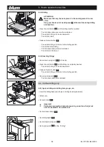
3.5.2) Setting the stop dimension
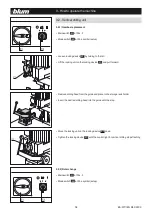
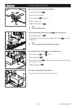
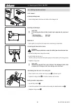
• Select a suitable screw (
E29)
depending on the desired drilling depth
• Turn screw to the desired dimension Z in the drill and lock using the counter nut
a) Drilling depth
=
13
mm
Work piece thickness
=
X
mm
=
> Z = X
b) Drilling depth
=
Y
mm
Work piece thickness
=
X
mm
=
> Z = X + 13 - Y
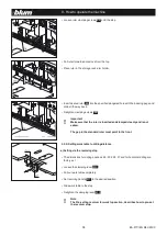
• Check dimension with a test drilling
• Label revolver handle
(E16)
using the included stickers
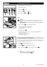
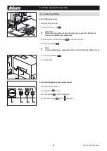
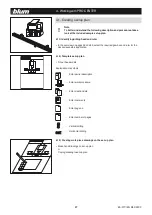
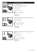
3.6 - Pre-setting revolver for work top setting
3.6.1) The dimensions for drilling positions
9.5
,
20
,
22.5
,
37
and for horizontal
drilling
(H)
are factory set.
• 3 additional dimensions can also be pre-set
• 3 stop rods
(E30)
are enclosed
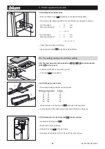
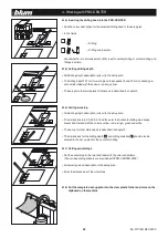
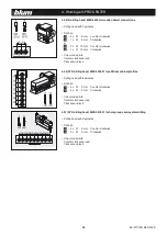
3.6.2) Cutting stop rods to size
• The desired drilling position should be pre-set:
Drilling position [mm]
X [mm]
5 - 37
0
37 - 62
25
62 - 87
50
87 - 112
75
112 - 125
90
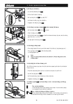
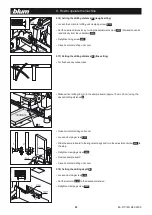
• Mark dimension X on the stop rod
(E30)
as shown in the top picture
• Cut the stop rod to the length using a hack saw and de-burr using a file
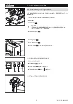
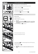
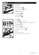
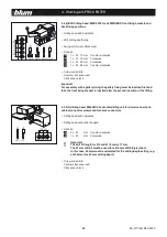
3.6.3) Screwing the re-sized stop rod
(E30)
into the revolver
• Loosen the clamping lever
(E10)
• Pull out work table completely
• Remove the cover
(E12)
in the work table
• Now fully screw the stop rod into a free drill hole in the revolver

