[H ie
Bekamatic SC pg. 23
r eingeben]
[H ier eingeben]
[H ier eingeben]
13.2.
Safety strips:
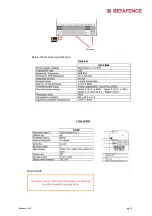
Wiring diagram for the safety edges fitted to the guiding post is presented below:
Check if all safety strips are functioning
Four safety strips are connected to CN60E module.
CN60E is connected to the “safety” input on the control board (input 5).
13.3.
Photocells:
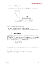
The photocells are connected on a BUS system. They need only two wires
without polarity.
Each set consists of a transmitter and receiver. Both devices must be set on
the same channel, this is achieved by selecting the correct dip switch.
You can program the photocells so that they work in:
Closing direction
Opening direction
Both directions
The photocells work in pairs and must be aligned so. A maximum of 7 pairs
can be fitted to one gate.
Follow the procedure as described below:
After alignment each individual interruption of the IR-beam
triggers “a line of the segment” an indication on the display.
Содержание Bekamatic SC 6000 Line
Страница 1: ...Bekamatic SC pg 1 Cantilever sliding gates Bekamatic SC 6000 Line Installation Manual ...
Страница 8: ...Bekamatic SC pg 8 4 1 Gates opening to the right ...
Страница 9: ...Bekamatic SC pg 9 4 2 Gates opening to the left ...
Страница 28: ... Hie Bekamatic SC pg 28 r eingeben Hier eingeben Hier eingeben This Manual is made on 13 05 2019 ...


