[H ie
Bekamatic SC pg. 13
r eingeben]
[H ier eingeben]
[H ier eingeben]
ATTENTION!
Ensure that cables and wires are not crushed between surfaces
while lowering and positioning the gate
onto
the ground
anchors.
7.
Installation of the lock post onto the ground
anchors:
1)
Remove the lock post from the gate wing and
suspend it over its ground anchors. Pull out
the cables from under the lock post and
connect the corresponding (colour-coded)
connectors together. We have provided one or
two boxes with connectors for these
connections.
2)
Push the cables back into the tube of the lock post until the
connectors are also in the tube. This will protect them against water
and will facilitate the uninstalling (replacement) of photocells.
3)
Position the lock post onto the ground anchors and install the upper
washers with nuts. Tighten the nuts slightly for temporary fixation.
8.
Alignment and
levelling of the gate:
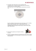
1)
Put the gate in manual (disengaged)
mode by turning the red sling
clockwise.
2)
Align the rear roller assembly and the
guiding post according to the gate
center axis line. Ensure that the wing
is running parallel through the
guiding post.
The guiding post and the rear roller assembly can be moved laterally
in the oblong holes of the base plates.
Once the alignment between the rear roller assembly and the guiding
post is complete, slightly tighten the ground anchor nuts of the guiding
post and rear roller assembly.
Check if the gate moves freely by hand over the complete span of
the wing during opening and closing. Do this slowly as not all
adjustments are done.
Содержание Bekamatic SC 6000 Line
Страница 1: ...Bekamatic SC pg 1 Cantilever sliding gates Bekamatic SC 6000 Line Installation Manual ...
Страница 8: ...Bekamatic SC pg 8 4 1 Gates opening to the right ...
Страница 9: ...Bekamatic SC pg 9 4 2 Gates opening to the left ...
Страница 28: ... Hie Bekamatic SC pg 28 r eingeben Hier eingeben Hier eingeben This Manual is made on 13 05 2019 ...


