


32
Multifunction Control Panel
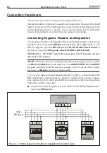
Figure 2.14 - Connecting the Telephone Line
Auxiliary Device (Open Collector)
KYO4, KYO8, KYO8W and KYO32
have 3 programmable Open-Collector
outputs (terminals 23 [
O1
], 24 [
O2
] and 25 [
O3
]). KYO8G, KYO8GW and
KYO32G have 5 programmable Open-Collector outputs (terminals 38[
O1
],
39[
O2
], 40[
O3
], 41[
O4
] and 42[
O5
]).
Kyo16D have 2 programmable Open-
Collector outputs (terminals 22 [
OC1
] and 23 [
OC2
]).
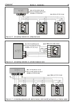
These terminals can be
set up as Normally Open (NO) or Normally Closed (NC), and can be activated
by one or more events (to be selected during the programming phase—refer to
the ‘PROGRAMMING FROM PC’ section for the list of events).
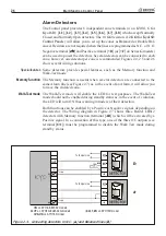
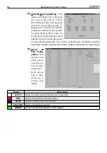
The wiring diagram in Figure 2.13 illustrates the operating principles of a NO
Open-Collector output (terminal [
O1
] on the Control panel) which will be
activated by the ‘Exit Delay’ event.
A
The IMQ-SECURITY SYSTEM approval applies only when the Ex-
pander OC Outputs are interfaced with relays, installed inside the Expander
box.
Figure 2.13 - Connecting an OC Output
5HOD\
&RQWDFWV
5HOq
Содержание KYO 32 M
Страница 1: ...0 1 7 167 7 21 0 18 ...
Страница 10: ...10 Multifunction Control Panel The NC2 TAST LED Keypad Figure 1 3 The NC2 TAST LED Keypad D D ...
Страница 11: ...11 Section 1 Identification of Parts The ICON KP LED Keypad Figure 1 4 The ICON KP LED Keypad D D ...
Страница 12: ...12 Multifunction Control Panel Ö Ö Ö Ö 0 1 01 2 3 42 2 1 0 4 01 1 1 5 675 8 5 68 65 8 5 9 5 8 04 04 1 1 1 04 ...
Страница 71: ...71 Section 3 Programming from PC 5 11 6 0 1 2 3 1 4 3 3 5 2 3 0 1 2 3 ...
Страница 88: ...ISTISBLEUNKYO 2 6 160108 P70 17 6 85 7 6 U O 01 02 5HF FOLQ LQ RU WLRQ ...


