


31
Section 2 - Installation
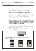
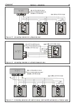
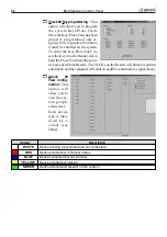
Figure 2.12 - Connecting the 24h Tamper Line
6,5(1
'(7(&725
Connecting the Tamper Line
G
G
G
G
G
- The Tamper Line terminals [AS] are not present on KYO16D Control
Panel.
To make a 24 H Tamper Line on KYO16D Control Panel:
1. Une an alarm zone
2. Program this zone as “24 H”
3. Program this zone as “Balanced 10 K”
4. Assign this zone to one or more partitions
The Control panel (except KYO16D) has a 24h 10K Balanced Tamper line (Termi-
nals 5 [
AS
] and 6 [
M
M
M
M
M
]). The Tamper terminals of the system peripherals must be
connected in series to these terminals. The wiring diagram in Figure 2.12 illustrates a
typical connection.
10 K
Ω
Ω
Ω
Ω
Ω
Balance resistor must be connected to the last device, as shown in
Figure 2.12.
Содержание KYO 32 M
Страница 1: ...0 1 7 167 7 21 0 18 ...
Страница 10: ...10 Multifunction Control Panel The NC2 TAST LED Keypad Figure 1 3 The NC2 TAST LED Keypad D D ...
Страница 11: ...11 Section 1 Identification of Parts The ICON KP LED Keypad Figure 1 4 The ICON KP LED Keypad D D ...
Страница 12: ...12 Multifunction Control Panel Ö Ö Ö Ö 0 1 01 2 3 42 2 1 0 4 01 1 1 5 675 8 5 68 65 8 5 9 5 8 04 04 1 1 1 04 ...
Страница 71: ...71 Section 3 Programming from PC 5 11 6 0 1 2 3 1 4 3 3 5 2 3 0 1 2 3 ...
Страница 88: ...ISTISBLEUNKYO 2 6 160108 P70 17 6 85 7 6 U O 01 02 5HF FOLQ LQ RU WLRQ ...


