


17
Section 2 - Installation
S
ECTION
2 - I
NSTALLATION
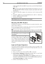
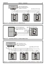
Mounting the Peripherals
The Main Unit
Refer to the
Main Unit Manual
for the respective installation instructions.
Mounting Keypads
A
Use of ICON/KP Keypads down-grades the IMQ-SECURITY SYSTEM Cer-
tification from Performance Level II to performance Level I.
Work carefully through the following steps:
1
. Remove the screws [
47
] and the frontplate.
2
. Lift the clip [
58
] and remove the PCB.
3
. Pull the wires through the cable entry [
57
].
4
. Drill the holes [
59a
], [
59b
] or [
59c
] for the backplate and snatch bracket
[
61
] (if necessary).
5
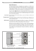
. If necessary, install the Snatch Microswitch [
56
]. Ensure that the Snatch
Microswitch lever is held firmly in position (pressed down) by the plastic
tooth on the Snatch bracket [
61
]. Using a screw, secure the Snatch bracket
to the wall.
NOTE - OMNIA/TAST-R and NC2/TAST Keypads are fitted with Snatch
Microswitches, which are enabled by securing the Snatch bracket [61] to
the wall by means of an anchor screw .
A
In order to comply with the standards outlined in Performance Level 11
of the IMQ-SECURITY SYSTEM certification, keypads must be fitted with
Snatch Microswitches.
6
. Replace the PCB and, if required, the Tamper Microswitch (for MIA or
ALISON Keypads), then connect to connector [
50
].
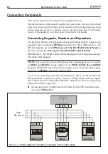
7
. Complete the connections between the terminal board [
53
] and Control
panel BPI Bus.
8
. Using the DIP switch strip [
51
], assign the Keypad Address
(refer to
‘Addressing Devices’
, further on in this section)
.
9
. Reattach the frontplate.
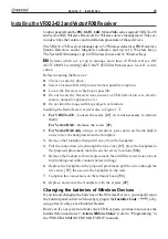
Mounting PROXI Proximity Readers
Work carefully through the following steps:
1
. Remove the screws [
47
] and the frontplate.
2
. Pull the wires through the cable entry [
57
].
3
. Drill the holes [
59a
] for the backplate.
4
. If necessary, install the Snatch Microswitch [
56
]. Ensure that the Snatch
Microswitch lever is held firmly in position (pressed down) by the plastic
Содержание KYO 32 M
Страница 1: ...0 1 7 167 7 21 0 18 ...
Страница 10: ...10 Multifunction Control Panel The NC2 TAST LED Keypad Figure 1 3 The NC2 TAST LED Keypad D D ...
Страница 11: ...11 Section 1 Identification of Parts The ICON KP LED Keypad Figure 1 4 The ICON KP LED Keypad D D ...
Страница 12: ...12 Multifunction Control Panel Ö Ö Ö Ö 0 1 01 2 3 42 2 1 0 4 01 1 1 5 675 8 5 68 65 8 5 9 5 8 04 04 1 1 1 04 ...
Страница 71: ...71 Section 3 Programming from PC 5 11 6 0 1 2 3 1 4 3 3 5 2 3 0 1 2 3 ...
Страница 88: ...ISTISBLEUNKYO 2 6 160108 P70 17 6 85 7 6 U O 01 02 5HF FOLQ LQ RU WLRQ ...


