89000004-200
KA 310 STC Installation Manual
Rev 0
Page 3-6
© Honeywell International Inc. Do not copy without express permission of Honeywell.
3.5.2.4
KA310 Installation Considerations in KAP 100 Flight Control System
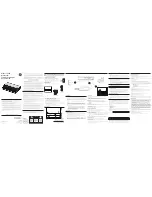
When installing the KA310 with the KI 300 to provide intended functions of the KG258 in KAP 100
autopilot system, refer to Figure 3-3 for a system depiction of the wiring that will be required.
Refer to Figure B-4 for Interconnect diagram.
AIRPLANE POWER
PRIMARY BUS
(28V OR 14V)
DECISION HEIGHT
ALERT
(OPTIONAL FOR
INSTALLATION WITH
RADAR ALTIMETER)
KC 190
(KAP 100 SYSTEM)
2 AMP
ELECTRONIC
ATTITUDE
INDICATOR
KA 310
Figure 3-3 Installation of KA310 in KAP 100 Flight Control System
3.6
ARINC 429 Interface
The KA 310 provides the following ARINC 429 interfaces:
Attitude output
Airdata output
Flight director input
The interface speed is a common setting for all interfaces and is set to high (100 kbps).
The following ARINC 429 labels are required for the flight director input:
Octal Label 140 - Flight Director - Roll (BNR label)
Octal Label 141 - Flight Director - Pitch (BNR label)
The following ARINC 429 labels contain the attitude data output:
Octal Label 203 – Baro-uncorrected Altitude (BNR label)
Octal Label 204 – Baro-corrected Altitude (BNR label)
Octal Label 206 – Indicated Airspeed (BNR label)
Octal Label 212 – Altitude Rate (BNR label)
Octal Label 324 – Pitch Angle (BNR label)
Octal Label 325 – Roll Angle (BNR label)
REF:
RELEASED FOR THE EXCLUSIVE USE BY: HONEYWELL EMPLOYEE AMERICAS
UP793797


