Technical Documentation
Rev. 01
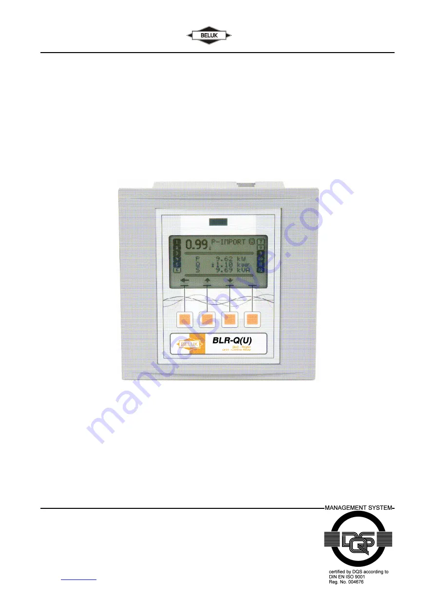
Power Factor Regulator
BLR-Q(U)
Beluk GmbH
Taubenstrasse 1
D-86956 Schongau
Germany
Tel.: +49/(0)8861/2332-0
Fax: +49/(0)8861/2332-22
e-mail:
[email protected]
http://www.beluk.de
REFERENCE GUIDE
POWER FACTOR REGULATOR
BLR-Q(U)


