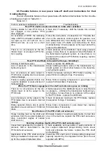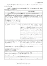
2122.6-0000010 OM
227
Table 6.12.1 continued
Error
code
Description, possible
problem
Failure inspection method
16
Failure in electronic unit.
Stabilized power supply
voltage, powering the
control panel is lower
than the required level.
Short circuit may occur in
the force and position
sensors sockets of RLL
caused by water entering
the sockets
Disconnect the main control panel from the common cable.
Measure stabilized power supply voltage of the terminals 6
(minus) and 4 (plus) of the control panel socket, which
shall make 9.5 - 10 V (with the engine running). If the sup-
ply voltage is low or in absence of it, check the reliability of
electronic unit socket connection. Disconnect the force
sensor and the position sensor of RLL one-by one (Figures
6.12.2, 6.12.3)
Moderate failures
22
Failure of the position
sensor. Breakage of the
sensor wire, the sensor
was not connected or ad-
justed
1. Faulty adjustment of the position sensor.
Disconnect the cable socket from the sensor. Unscrew the
sensor. Lift the LL in an uppermost position by remote but-
tons or button “lift” on the solenoid (bottom solenoid).
Screw the sensor in by hand as far as it may go and un-
screw by 2 turns. Connect the cable socket to the sensor.
Lower and lift in an uppermost position the LL by means of
the control panel. Lift indicator shall be out. If the indicator
is still flashing, make the position sensor further by 1/6 of a
turn. Check the system operation again. If it is necessary
(lift indicator is not out in an uppermost position), make the
position sensor a little bit further and try to check again. If
the adjustment was made in a proper manner, LL shall be
lowered and lifted by means of the control panel to the ex-
treme positions. The lift indicator shall be out in an upper-
most position
2. Failure of the position sensor.
2.1 To check the operability of “BOSCH” position sensor, dismount it
from the tractor. According to the electric circuit diagram of the RLL con-
trol system (figure 6.12.2, the position sensor connection), it is required to
supply voltage of 10V (in case the power supply unit is not available, volt-
age of 12V can be supplied from the accumulator battery for a short
moment) to: output 1 “load” (minus) and to output 3 “+” (plus) and press-
ing the sensor migrating rod by a finger, measure the voltage at the sen-
sor output by the testing apparatus: between output 2 – “signal” and out-
put 1 – “minus”. While the full sensor rod (core) shifting, the voltage at the
sensor output shall be measured within the limits from 0.2 to 0.75 of the
value of voltage supplied to the sensor. If the specified parameters are
broken, it is required to mount a new sensor on the tractor and adjust it
properly. Numbers of sensor outputs are indicated on the cable socket
connector which is attached to the position sensor.
2.2 It is impossible to check the
ДП
-01 sensor manufactured by the
works “Izmeritel”, operability by means of dismounting it from the tractor. If
carrying out adjustments failed to eliminate the
ДП
-01 sensor failure, it is
required to mount a new
ДП
-01 sensor on the tractor and adjust it prop-
erly.
3. Failure (breakage) of the cable in sensor circuit.
Check the cable according to the diagram (figures 6.12.2, 6.12.3)
https://tractormanualz.com/


