2122.6-0000010 OM
126
4.3.3 RLL components adjustment rules
4.3.3.1 Buckles
Buckles are used to limit side swaying of RLL lower links in transport and in operat-
ing position. Your tractor can be equipped with telescopic turnbuckles.
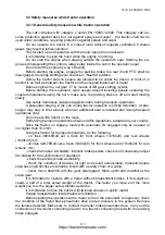
Buckles 2 (figure 4.3.3) are fixed with one end to eye lugs 3 of lower links 4. The
other end of buckles with hinge joints is fixed into the brackets of buckles 1 with the help of
pins. The brackets of buckles 1 are fixed on the lower part of RLL semi-axle tubes.
1 – buckle bracket; 2 – buckle; 3 – eye lug; 4 – lower link.
Figure 4.3.3
– Installing of buckles in RLL
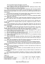
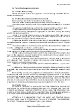
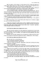
The buckle consists of screw 1 (figure 4.3.4), guiding pin 2, slide piece 4 and linch
pin 3.
Guiding pin 2 has a through groove on the side surface and a through hole in the
surface perpendicular to it.
Slide piece 4 has two through holes in one plane.
а
) buckle locked
b) buckle unlocked
1 – screw; 2 – guiding pin; 3 – linch pin; 4 – slide piece.
Figure 4.3.4
– Setting of buckles
While tractor operation buckles shall always be locked in one of the two positions:
-
buckle
locked;
-
buckle unlocked.
Setting of buckles shall be carried out with the implement mounted on lower links
rear ends and lowered onto the supporting surface.
Setting of “buckle locked” shall be carried out in the following order:
- match the hole for linch pin 3 in guiding pin 2 with the hole in slide piece 4;
- in case of mismatch, turn guiding pin 2 clockwise or counterclockwise until the
holes match;
- insert linch pin 3 into the hole and fix it with the spring clip.
https://tractormanualz.com/

