2122.6-0000010 OM
182
5.4.2.12.2.4 Check / adjustment of clutch disengaged state sensor
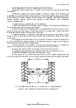
Adjustment of sensor 1 triggering (figure 5.4.23) shall be carried out with the engine running.
Moving sensor 1 together with bracket 5 in its slot and adjusting position of bolt 2 adjust triggering
(contact closure) of sensor 1.
After adjustment of the clutch disengaged state sensor 1 (figure 5.4.23) clearance S be-
tween the housing of sensor 1 and the head of adjusting bolt 2 shall be from 0.5 to 1.0mm with
the clutch fully depressed.
After the adjustment is completed secure bracket 5 by bolts 3, bolt 2 shall be secured by
the nut.
1 – sensor of clutch disengaged state; 2 – adjusting bolt; 3 – bracket attaching bolts; 4 – clutch
pedal; 5 – bracket.
Figure 5.4.23 – Clutch disengaged state sensor assembly
5.4.2.12.2.4 Check of declutching cleanliness
After performing the above mentioned adjustments of clutch control, it is required to
check declutching cleanliness, for which do the following:
- engage the parking brake;
- start the engine and set diesel rated speed (1400±100) min
-1
;
- fully depress the clutch pedal and min in 5 sec engage GB ranges, the activation of
which shall be “clear” – without unwanted sounds and rattle.
In case there are unwanted sounds or rattle, it is required to check and if necessary,
make adjustments specified in subclause 5.4.2.12.2.1 again.
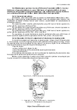
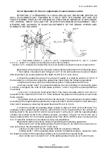
Pedal 7 (figures 5.4.21 and 5.4.22) shall not bear against panel 12 (figures 5.4.21 and
5.4.22).
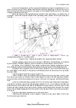
After bleeding of the hydraulic system with the engine stopped, the total pedal 7 free
travel shall make size
Е
that corresponds to withdrawal of hydraulic booster 28 piston to size
И
from end face of hydraulic booster. When the pedal is fully pressed, withdrawal of hydraulic
booster piston shall make not less than size K from the end face of hydraulic booster.
Clutch disengaged
(pedal fully depressed)
Clutch engaged
(pedal released)
Clutch disengaged
(pedal fully depressed)
https://tractormanualz.com/


