2122.6-0000010 OM
179
5.4.2.12
Operation 31. Check / adjustment of clutch control
5.4.2.12.1 Check of clutch control
Check the condition of the expansion tank, main and operating cylinders, hydraulic
booster and pipelines. Brake fluid or oil leakages are not allowed. Clean the control drive and
the clutch control pedal from dirt and outside particles.
Check the clearance between the clutch release bearing and release levers: when the
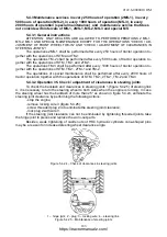
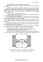
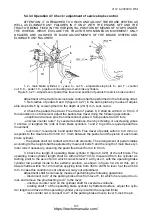
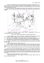
engine is not running, the total pedal free travel 7 (figures 5.4.21 and 5.4.22) shall make
size E that corresponds to withdrawal of hydraulic booster piston 28 to size
И
from end surface
of hydraulic booster.
If necessary, two people shall adjust clutch control according to subsection 5.4.2.12.2
“Adjustment of clutch control”.
ATTENTION: ONLY DEALERS ARE ALLOWED TO ADJUST AND BLEED CLUTCH
CONTROL!
5.4.2.12.2 Adjustment of clutch control
5.4.2.12.2.1 The rules for adjustment of clutch control
Adjustment of clutch control shall be performed in the following order:
1. Adjustment of clearance “B” (figures 5.4.21 and 5.4.22) between piston 10 and
pusher 9 of main cylinder 11:
- bring pedal 7 to size “
Д
” by means of bolt 3, tighten nut 4 with a torque from 10 to 16
Nm;
- by screwing and unscrewing pusher 9 try to achieve, that shift of pedal 7 from its initial
position to the moment of touching pusher 9 into piston 10, measured on the center of pedal
casing, makes size “
Г
”;
- tighten up nut 8 with a torque from 30 to 50 Nm and cotter pin 6.
2. Adjustment of clearance “
Ж
” (figures 5.4.21 and 5.4.22) between rod 26 of working
cylinder 25 and pusher 27 of hydraulic booster 28:
- remove operating cylinder 25 from bracket 14 after taking out pin 15;
- set rod 26 of cylinder 25 into the extreme right position until stops against cover 22;
- bring cylinder 25 to touch pusher 27 of hydraulic booster 28 lightly and by screwing
and unscrewing support 16 match the holes of the support and bracket 14, after which screw
in support 14 by ½ revolutions, mount pin 15;
- tighten nut 21 with a torque from 18 to 30 Nm and cotter pin 15.
3. Adjustment of clearance between the clutch release bearing and release levers:
- disconnect rod 30 (figures 5.4.21 and 5.4.22) from lever 35 after taking pin 34 out;
- unlock yoke 33;
- turn lever 35 contraclockwise until the release bearing stops against release levers
and rotating yoke 33 match the holes of the lever and yoke, after which screw it in by 5…5,5
revolutions and connect them with the lever by means of pin 34;
- tighten up nut 31 with a torque from 50 to 70 Nm without letting link 30 turn, cotter pin
34.
4. Bleed the hydraulic system of clutch control according to clause 5.4.2.12.2.2 or
5.4.2.12.2.3 of the present operator’s manual.
5. Check and if necessary adjust clutch disengaged state sensor in accordance with clause
5.4.2.12.2.4 of this manual.
5.4.2.12.2.2 Bleeding of the hydraulic system of clutch control with the main and operat-
ing cylinders manufactured by OJSC “Gomel Works “Hydraulic drive”
Before bleeding, fill tank 1 (figure 5.4.21) of main cylinder 11 with brake fluid.
https://tractormanualz.com/


