User Guide Revision 1.12
56
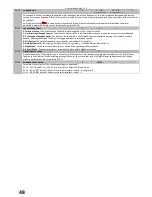
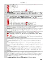
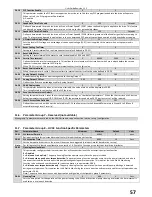
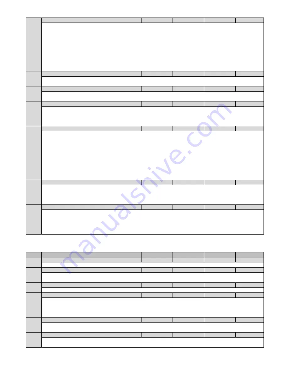
P5-08
Fieldbus Module PDO4
0
7
1
-
When using an optional Fieldbus interface, this parameter configures the parameter source for the 4th process data word transferred
from the drive to the network master during cyclic communications:
0 : Output Power – Output power in kW to two decimal places, e.g. 400 = 4.00kW
1 : Output Power – Output power in kW to two decimal places, e.g. 400 = 4.00kW
2 : Digital Input Status – Bit 0 indicates digital input 1 status, bit 1 indicates digital input 2 status etc
3 : Analog Input 2 Signal Level – 0 to 1000 = 0 to 100.0%
4 : Drive Heat-sink Temperature – 0 to 100 = 0 to 100°C
5 : User Register 1 – Can be accessed by PLC program or group 9 parameters
4 : User Register 2 – Can be accessed by PLC program or group 9 parameters
7 : P0-80 Value - P0-80 value can be selected by P6-28
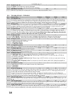
P5-09
BACnet Device Instance Number (Low)
0
65535
1
-
Drive instance number within the BACnet network. Combined with P5-10 the value entered must represent a unique value with the
BACnet system / network. P5-09 represents the lower 16 bits of the device instance number. Device instance number 22 bit total.
P5-10
BACnet Device Instance Number (High)
0
63
0
-
Drive instance number within the BACnet network. Combined with P5-09 the value entered must represent a unique value with the
BACnet system / network. P5-10 represents upper 6 bits of the device instance number. Device instance number 22 bit total.
P5-11
BACnet Maximum Masters
0
127
127
-
Parameter defines the maximum address of any BACnet masters that can exist on the current local MSTP BACnet network. When the
device is polling for the next master in the network it will not poll about the value set in P5-11. For example, if the value is set to 50
then when the drive finishes communicating and needs to pass control to the next master it will poll up to address 50 looking for a
response before rolling back to address 0.
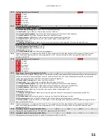
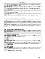
P5-12
Fieldbus Module PDO3
0
7
0
-
When using an optional Fieldbus interface, this parameter configures the parameter source for the 3rd process data word transferred
from the drive to the network master during cyclic communications:
0 : Motor Current – With one decimal place, e.g. 100
1 : Output Power – Output power in kW to two decimal places, e.g. 400 = 4.00kW
2 : Digital Input Status – Bit 0 indicates digital input 1 status, bit 1 indicates digital input 2 status etc
3 : Analog Input 2 Signal Level – 0 to 1000 = 0 to 100.0%
4 : Drive Heat-sink Temperature – 0 to 100 = 0 to 100°C
5 : User Register 1 – Can be accessed by PLC program or group 9 parameters
4 : User Register 2 – Can be accessed by PLC program or group 9 parameters
7 : P0-80 Value - P0-80 value can be selected by P6-28
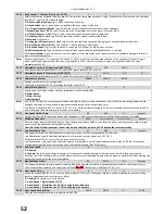
P5-13
Fieldbus Module PDI4
0
1
0
-
When using an optional Fieldbus interface, this parameter configures the parameter source for the 4th process data word transferred
from the network master to the drive during cyclic communications:
0: User ramp time – In second with two decimal places.
1: User Register 4 – Can be accessed by PLC program or group 9 parameters
P5-14
Fieldbus Module PDI3
0
2
0
-
When using an optional Fieldbus interface, this parameter configures the parameter source for the 3rd process data word transferred
from the network master to the drive during cyclic communications:
0 : Not used - No function
1 : User PID Reference - 0 to 1000 = 0% to 100.0%
2 : User Register 3 – Can be accessed by PLC program or group 9 parameters
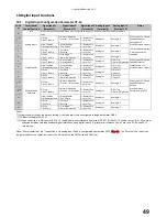
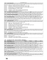
11.5.
Parameter Group 6 – Advance Feature configuration
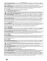
Par
Parameter Name
Minimum
Maximum
Default
Units
P6-01
Firmware Upgrade Enable
0
1
0
-
Enables drive firmware to be updated. Refer to advanced user guide before attempting to update drive firmware.
P6-02
Auto-Thermal Management
4
16
4
kHz
The drive will automatically reduce the output switching frequency at higher heat-sink temperature, to reduce the risk of an over
temperature trip. The minimum switching frequency that the drive output can be reduced to is the limit set in P6-02
P6-03
Auto Reset Time Delay
1
60
20
Seconds
Sets the delay time which will elapse between consecutive drive reset attempts when Auto Reset is enabled in P2-36
P6-04
User Relay Hysteresis Band
0
1
0
-
This parameter works in conjunction with P2-11 and P2-13 = 2 or 3 to set a band around the target speed (P2-11 = 2) or zero speed
(P2-11 = 3). When the speed is within this band, the drive is considered to be at target speed or Zero speed. This function is used to
prevent “chatter” on the relay output if the operating speed coincides with the level at which the digital / relay output changes state.
e.g. if P2-13 = 3, P1-01 = 50Hz and P6-04 = 5%, the relay contacts close above 2.5Hz
P6-05
V/F Characteristic Select
0
1
0
-
Selects the V/F characteristic used for the motor control.
P6-05 = 0 selects a quadratic characteristic, P6-05 =1 selects a linear characteristic
P6-08
Master Speed Reference Frequency
0
5
0
kHz
When the motor speed reference is to be controlled by a frequency input signal (connected to Digital input 3), this parameter is used
to define the input frequency which corresponds to the maximum motor speed (set in P1-01).
Содержание HVAC H2
Страница 1: ......
Страница 72: ...User Guide Revision 1 12 72 82 H2MAN BE_V1 11...


