User Guide Revision 1.12
34
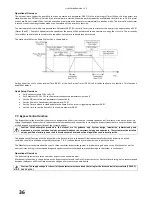
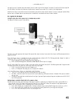
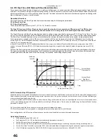
A detection tolerance for the Load Profile Monitoring Function is set within parameter P8-07. Parameter P8-07 (Load Profile Monitoring
Function Bandwidth) is set as a current (amps) value and is then applied to the standard operating profile stored within the drive to allow for
acceptable variations in the motor current measurement. The value entered is applied symmetrically to the nominal current value so totally
bandwidth is 2 x P8-07. The Current values measured during the auto-tune are recorded to parameter P0-58 for reference.
In addition to a bandwidth of tolerance being applied to the standard operating profile (P8-07) a trip delay or time limit can also be specified
for operation on the drive within the over torque or under torque regions. This time is set within parameter P8-08 (Load Profile Monitoring
Function Trip Delay). This parameter can be set to avoid nuisance tripping whilst the load is in a temporary or transitional state.
The drive will trip immediately on detecting an under / over torque condition for a time period greater than that set in P8-08 and will disable
output to the motor with coast to stop. The trip will be displayed on the OLED display and can be reset by pressing the Keypad STOP key.
The drive can be set to run an automatic pump cleaning function once the Load Profile Monitoring Function has detected an over-torque
condition. See section 7.5, Pump Clean Function for more information.
Trip Codes:
: Over-Torque Level Detected resulting in drive trip (Fault code 24)
: Under-Torque Level Detected resulting in drive trip (Fault code 25)
Quick Setup Overview:
Read Caution note associated with this function (above)
Set the maximum and minimum speed limits for the drive (P1-01 & P1-02).
Set Basic parameters P1-03 to P1-10. Energy Optimiser P1-06 must remain disabled.
Set Parameter P1-14 = 101 to allow access to advanced parameters in menu 8
Enable the Load Profile Monitoring Function by setting P8-06
o
0: Disabled
o
1: Low Load Detection Enabled (Belt Failure / Dry Pump / Broken Impeller)
o
2: High Load Detection Enabled (Pump Blockage)
o
3: Low and High Current Detection
Set an acceptable tolerance bandwidth in P8-07. Set a high bandwidth initially and monitor current during normal operation to
determine tighter levels if required.
Enable the drive and allow the automatic measurement sequence to run.
Should some nuisance tripping occur Increase the Load Profile Monitoring Function Trip Delay in P8-08. If tripping still occurs then
repeat the automatic measurement sequence.
7.5.
Pump Clean Function
The Pump cleaning function is used to remove blockages from a pump. The pump clean function can be manually triggered by a digital input or
can be triggered automatically on start up, or when the drive detects an over-torque condition (due to blockage forming).
When the Pump cleaning cycle is activated the drive will perform a predefined motion profile (cleaning cycle) in order to attempt to remove
the blockage.
Operational Overview:
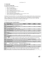
The pump cleaning function is enabled or disabled and its automatic triggering defined by parameter P8-03 Pump Cleaning Function
Configuration. Options included for parameter P8-03 include:
0. Disabled
1. Pump cleaning function activated on drive start up
2. Pump cleaning function activated on drive start up or over-torque detection
3. Pump cleaning function activated on over-torque detection
If either option 1 or option 2 is selected for P8-03 then the drive will run the pump cleaning cycle immediately on drive enable (enable
command given of digital input 1, drive terminal 2). Once the pump cleaning cycle is complete the drive will return to normal set-point control.
If either option 2 or option 3 is selected for P8-03 then the Load Profile Monitoring function must be set-up in order to detect an over-torque
condition. Set up the Load Profile Monitoring function as per the instructions in this guide.
Please see section 7.4 – Load Profile Monitoring
Function.
When the Pump cleaning function is triggered from an over-torque condition then the drive does not go into an over-torque trip
following an over torque condition but instead automatically runs the pump clean function. On exiting the pump clean function the drive will
return to its normal operating set-point. If any further over-torque events occur within 60 seconds of a pump clean function finishing then this
will then cause an over-torque trip.
Further attempts to clean the pump (up to a maximum of 5 attempts) can be programmed through the Automatic Trip Reset function (see P2-
36 – Start Mode Select). When auto-restarting from an over-torque trip the drive will automatically run the pump clean function provided the
pump clean function is enabled.
If a digital input is assigned to this function then it will activate the pump clean sequence regardless of the setting of parameter P8-03 (Pump
Cleaning Function Configuration). When the Pump Clean Function is initiated via an input to the drive, the drive will ramp immediately from its
current operation speed to the first speed defined by the pump clean cycle using applicable ramp rates.
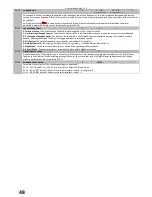
The digital input assignment for the pump cleaning function is defined through P9-42 – Clean trigger input edge. Menu 9 can only be accessed
using the advanced level security access (default P1-14 – 201). Set P9-42 with the value associated with the digital input to be used.
Содержание HVAC H2
Страница 1: ......
Страница 72: ...User Guide Revision 1 12 72 82 H2MAN BE_V1 11...


