User Guide Revision 1.12
61
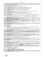
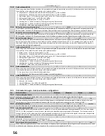
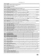
P0-29
Drive Type
-
-
-
-
Displays the type details of the drive: Three entry display:
First display = Frame size and input voltage level
Second display = Power rating
Third display = Output Phase Count
P0-30
Serial Number
-
-
-
-
Displays the unique serial number of the drive. Dual entry display:
First display = Serial number (MSB), Second display = Serial number (LMSB)
P0-31
Run Time Since Date of Manufacturer
0
-
-
HH:MM:SS
Two entry display: First display shows hours. Second display shows minutes and seconds
Displays the total operating time of the drive.
P0-32
Run Time Since Last Trip 1
0
99999H
-
HH:MM:SS
Two entry display: First display shows hours. Second display shows minutes and seconds
Displays the total operating time of the drive since the last fault occurred. Run-time clock stopped by drive disable (or trip), reset on
next enable only if a trip occurred. Reset also on next enable after a drive power down.
P0-33
Run Time Since Last Trip 2
0
99999H
-
HH:MM:SS
Two entry display: First display shows hours. Second display shows minutes and seconds
Displays the total operating time of the drive since the last fault occurred. Run-time clock stopped by drive disable (or trip), reset on
next enable only if a trip occurred (under-volts not considered a trip) – not reset by power down / power up cycling unless a trip
occurred prior to power down.
P0-34
Run Time Since Last Disable
0
99999H
-
HH:MM:SS
Two entry display: First display shows hours. Second display shows minutes and seconds
Displays the total operating time of the drive since the last Run command was received.
P0-35
Fan Run Time
0
99999H
-
HH:MM:SS
Displays the total operating time of the drive internal cooling fans.
Two entry display: First display shows user resettable time (reset with P6-22). Second display shows none resettable time.
This is used for scheduled maintenance information
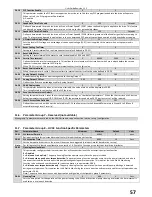
P0-36
DC Bus Voltage Log (256ms)
-
-
-
-
Diagnostic log for DC bus voltage. Values logged every 256mS with 8 samples total. Logging suspended on drive trip.
P0-37
DC Bus Voltage Ripple Log (20ms)
-
-
-
-
Diagnostic log for DC bus voltage ripple. Values logged every 20mS with 8 samples total. Logging suspended on drive trip.
P0-38
Heatsink Temperature Log (30s)
-
-
-
-
Diagnostic log for heatsink temperature. Values logged every 30S with 8 samples total. Logging suspended on drive trip.
P0-39
Ambient Temperature Log (30s)
-
-
-
-
Diagnostic log for drive ambient temperature. Values logged every 30S with 8 samples total. Logging suspended on drive trip.
P0-40
Motor Current Log (256ms)
-
-
-
-
Diagnostic log for Motor Current. Values logged every 256mS with 8 samples total. Logging suspended on drive trip.
Note:
The above parameters (P0-36 to P0-40) are used to store the history of various measured levels within the drive at various regular
time intervals prior to a trip. The values are frozen when a fault occurs and can be used for diagnostic purposes.
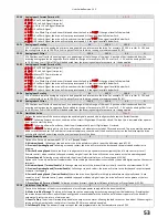
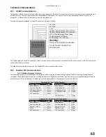
P0-41
Over Current Fault Counter
0
-
0
-
P0-42
Over Voltage Fault Counter
0
-
0
-
P0-43
Under Voltage Fault Counter
0
-
0
-
P0-44
Heatsink Over Temperature Fault Counter
0
-
0
-
P0-45
Brake Chopper Short Circuit Fault Counter
0
-
0
-
P0-46
Ambient Over Temperature Fault Counter
0
-
0
-
Note
These parameters (P0-41 to P0-46) contain a record of how many times certain critical faults have occurred during a drives operating
lifetime. This provides useful diagnostic data
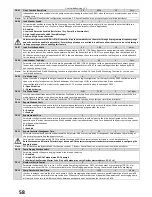
P0-47
I/O comms fault counter
0
-
0
-
Displays the number of communication errors detected by the I/O processor in messages received from the power stage processor
since the last power up
P0-48
DSP comms fault counter
0
-
0
-
Displays the number of communication errors detected by the Power Stage processor in messages received from the I/O processor
since the last power up
P0-49
Modbus RTU / BACnet Fault Counter
0
-
0
-
This parameter is incremented every time an error occurs on the Modbus RTU communication link. This information can be used for
diagnostic purposes.
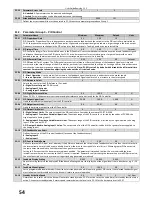
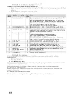
P0-51
Last Fire Mode Activation Time
-
-
-
Hours
Parameter contains a start time for the last Fire Mode event (see section 7.8 – Fire Mode Function). Value recorded in P0-51 is taken
from Drive Lifetime Operating Time parameter (P0-31)
P0-52
Fire Mode Activation Period
-
-
-
Hours
Parameter contains a record of the number of minutes that the drive has been run in Fire Mode (see section 7.8 – Fire Mode
Function).
P0-53
Current Phase U offset and Reference
-
-
-
-
Internal Value, Contact your local Drive Distributor
P0-54
Current Phase V offset and Reference
-
-
-
-
Internal Value, Contact your local Drive Distributor
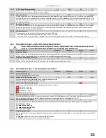
Содержание HVAC H2
Страница 1: ......
Страница 72: ...User Guide Revision 1 12 72 82 H2MAN BE_V1 11...

