User Guide Revision 1.12
36
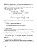
Operational Overview:
The time period to trigger the pump Stir function is entered into parameter P8-01 (Stir Function Integral Timer). When the drive enters into
standby mode (see PID control, section 8) an internal timer is started. When the timer exceeds the user defined time limit set in P8-01 a preset
motion profile is activated. When function execution is completed the drive returns immediately to standby mode. The internal function timer
is reset by the drive exiting standby mode or on completion of the pump Stir function.
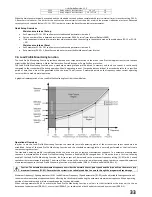
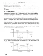
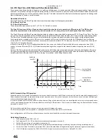
The motion profile is set within two parameters. Parameter P8-02 (Stir Activity Timer) sets the time that the pump is to be operated and P2-07
(Preset Speed 7 – Pump Stir Speed) sets the speed that the pump will be accelerated to and operate at during the stir cycle. The stir activity
time includes the time take to accelerate to speed but not the time to decelerate back to stop.
The motion profile for the Pump Stir function is shown below:
Setting either the Stir Function Interval Time (P8-01) or the Stir Activity Timer (P8-02) to 0 disables the Pump Stir function. This function is
disabled at default.
Quick Setup Overview:
Set Basic parameters P1-01 to P1-10.
Set Parameter P1-14 = 101 to allow access to advanced parameters in menu 8
Set the PID control menu 3 parameters (see section 8)
Set the Pump Stir Speed required in parameter P2-07
Set the Time to elapse in standby before the Pump Stir Function is triggered in parameter P8-01.
Set the time to run the Pump Stir Function in parameter P8-02
7.7.
Bypass Control Function
The Bypass Control function allows the motor to be operated either from the drive (variable speed control) or direct on line on the incoming
supply (fixed speed). Bypass control requires external components and connection in creating the bypass system that are not provided as part
of the drive and are the responsibility of the system designer.
Caution: Circuit examples provided in this manual are for guidance only. System design, installation, commissioning and
maintenance must be carried out only by personnel who have the necessary training and experience. The system must be installed
only by qualified electrical persons and in accordance with local and national regulations and codes of practice.
The bypass control function with the drive allows the drive to switch in the bypass circuit automatically should the drive trip on a fault
condition, should Fire Mode be activated (see section 7.8 - Fire Mode function) or manually via an input to the drive.
The Manufacturer recommended the use of a three contactor bypass arrangement in implementing a bypass circuit. Mechanical as well as
electrical inter-locking is recommended to guard against contactor failure and to prevent damage to the system in such events.
Operational Overview:
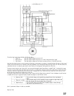
The basic configuration for a three contactor bypass circuit is shown below.
Mechanical Interlocking is shown between the Bypass contactor and the Drive Output contactor. Electrical Interlocking is also recommended
between the Bypass and Drive Output contacts using auxiliary contacts on each device
.
Caution: The supply voltage for the coil of the contactors must not exceed the rating for the drive control relays contacts (250V AC /
30V DC @ 5A)
Содержание HVAC H2
Страница 1: ......
Страница 72: ...User Guide Revision 1 12 72 82 H2MAN BE_V1 11...

