User Guide Revision 1.12
38
Bypass Mode on Fault is enabled by setting parameter P8-11=1 (enabled). Once enabled the drive will switch to bypass mode in the event of a
trip or fault occurring on the drive. When a trip occurs the drive will immediately open the drive output contactor (drive output already
disabled due to trip), wait a time (defined by P8-13) and then close the bypass contactor. The motor will remain under Bypass control until the
enable/run input is removed from the drive (drive control terminal 2) at which point the Bypass contactor will be opened. When the
run/enable input is closed again the drive will attempt to run under drive control (drive output contactor closed).
It is required that Spin Start (P2-26) be enabled for this function.
Bypass on Fire Mode.
Bypass on Fire Mode is enabled by setting parameter P8-12=1 (enabled). Once enabled, the drive will switch to bypass mode in the event of
the fire mode input becoming active (true). Fire Mode should be configured (see section 7.8. Fire Mode Function) and an input assigned either
through parameter P1-13 or through menu 9 (P9-32) prior to enabling Bypass on Fire Mode.
When the Fire Mode input becomes true the drive will immediately disable its output and open the drive output contactor, wait a time
(defined by P8-13) and then close the bypass contactor. The motor will remain under bypass control until the fire mode input is deactivated.
When the Fire Mode input is deactivated the bypass contactor will be opened, there will be a short delay (defined by P8-13) and the Drive
Output contactor will close. Provided the enable input is still present then the drive will take over operation of the motor.
It is required that Spin Start (P2-26) be enabled for this function.
Bypass on Input
Bypass mode on Input is enabled by assigning a bypass trigger input in menu 9. Set parameter P9-13 (Bypass Trigger Input) to one of the
available digital inputs. Once an input is assigned the drive will switch to bypass mode in the event of that input becoming active (true).
When the bypass trigger input becomes true the drive will immediately disable its output and open the drive output contactor, wait a time
(defined by P8-13) and then close the bypass contactor. The motor will remain under bypass control until the bypass trigger input is
deactivated. When the bypass trigger input is deactivated the bypass contactor will be opened, there will be a short delay (defined by P8-13),
the Drive Output contactor will close and the drive will take over operation of the motor.
If the enable input is removed from the drive then the drive will switch off whichever of the two output contactors is currently on. When the
drive is re-enabled the drive will look at the status of the bypass input to determine which of the output contactors to operate.
It is required that Spin Start (P2-26) be enabled for this function.
In all modes of operation the time period between one of the output contactors switching off and the other switching on is defined by
parameter P8-13 (Bypass Contactor Changeover Time). This parameter should be set with a value that ensures the first contactor has time to
clear prior to an attempt being made to switch in the second contactor. Additional mechanical or electrical inter-locking should also be
provided.
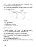
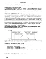
The Drive OLED display will show the following indication whenever bypass mode is activated by the drive control.
Quick Setup Overview:
Set Basic parameters P1-01 to P1-10.
Set Parameter P1-14 = 201 to allow access to advanced parameters in menu 8 & 9
Set time delay between switch over of output contactors to safe limit in parameter P8-13 (default 2S).
If Bypass required on Fault:
Set bypass mode of fault P8-11 to 1 (Enabled)
If Bypass required on Fire:
Go through Fire mode set up procedure (section 7.8) prior to enabling Fire Mode Bypass Function.
Set bypass mode of fault P8-12 to 1 (Enabled)
If Bypass required on Input:
Set bypass trigger input parameter P9-43 to an available digital input
Note: To set menu 9 parameters P1-13 must be set to 0 and input functions programmed manually.
7.8.
Fire Mode Function
The Fire Mode function is designed to ensure continuous operation of the drive until either the Fire Mode input is removed or the drive is no
longer capable of sustaining operation. It is used in applications where an input is provided to the drive from a fire control system in the event
of a fire in the building and drive operation is required to be maintained for the longest possible period in order to clear smoke or maintain air
quality within that building.
Operational Overview:
The Fire Mode function is a dedicated digital input function within the drive control software. An input can be assigned to activate the drive
Fire Mode function in one of the following ways:
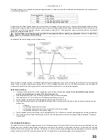
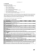
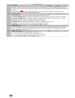
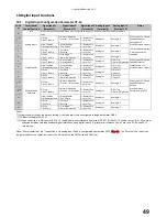
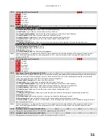
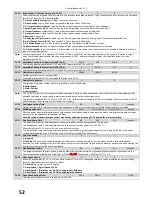
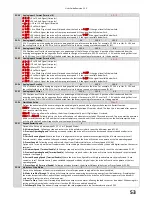
P1-13: Fire Mode can automatically be configured on digital input 2 by selecting values 4, 8, or 13 in parameter P1-13. (see
section 10.1 – Digital input configuration parameter.
Содержание HVAC H2
Страница 1: ......
Страница 72: ...User Guide Revision 1 12 72 82 H2MAN BE_V1 11...

