User Guide Revision 1.12
33
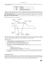
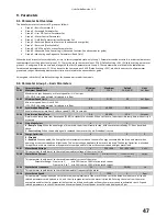
P2-15
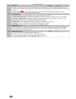
Relay output 1 function select
14 / 15
10
P2-18
Relay output 2 function select
16 / 17 / 18
10
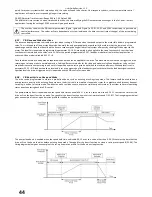
When the maintenance interval has expired and the scheduled service has been completed the service interval timer is reset by setting P6-25 =
1, Reset Service Indicator. The timer for the next service interval starts from the point at which the previous indication was reset. Advanced
security access is required (default P1-14 = 201) in order to access the Reset Service Indicator parameter.
Quick Setup Overview:
Maintenance Interval Set-up
Set Parameter P1-14 = 201 to allow access to advanced parameters in menu 6
Set the number of hours between services in parameter P6-24, Service Timer Interval (Default 5000).
If a drive output is required to indicate that maintenance is due then configure the output based on the table above (P2-15 or P2-18
= 10).
Maintenance Interval Reset
Set Parameter P1-14 = 201 to allow access to advanced parameters in menu 6
Set parameter P6-25 = 1, Reset Service Indicator to reset the Maintenance Timer Interval.
7.4.
Load Profile Monitoring Function
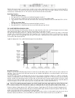
The Load Profile Monitoring Function provides under and over torque protection to the driven load. Practical applications for the function
might include Belt Snap detection, Motor Stall detection, Pump Blockage, or Pump Dry Run protection.
The Load Profile Monitoring Function uses a standard operating torque profile stored in memory and the drive current is continuously
compared to the standard profile during operation. Should operating current / torque deviate outside of the standard profile for a specified
period of time then a trip will be generated within the drive. The drive uses 5 measured points on the frequency versus current operating
curve in order to model normal operation.
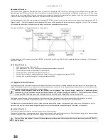
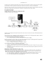
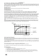
A graphical representation of the Load Profile Monitoring Function is shown below:
Operational Overview:
In order to use the Load Profile Monitoring Function the standard (normal) operating profile of the drive current versus speed must be
established. Set-up of the Load Profile Monitoring Function and the standard operating profile is normally performed as the final step in
commissioning the system.
The standard operating profile is established within the drive using an automatic measurement sequence. The automatic measurement
sequence is activated when the Load Profile Monitoring Function is enabled (P8-06 changed from 0). When the drive is first run, following
enable of the Load Profile Monitoring Function, the drive output will be ramped to the maximum frequency setting (P1-01) with 5 evenly
spaced current measurements recorded. The drive will then return to the normal set-point operating speed. In order to repeat the automatic
measurement sequence the Load Profile Monitoring Function must be disabled (P8-06 = 0) and re-enabled (P8-06 <> 0).
Caution: The automatic measurement sequence over-rides the normal drive set-point speed and the drive will run the motor up to
maximum frequency (P1-01). Ensure that the system is in a suitable condition to operate through the programmed speed range.
Maximum Frequency / Speed parameter (P1-01) and Minimum Frequency / Speed parameter (P1-02) can be adjusted following execution of
the automatic measurement sequence without affecting the results obtained during the automatic measurement sequence. When operating
outside of the maximum and minimum speed range the function is disabled.
When setting parameter P8-06 to activate the Load Profile Monitoring Function a value is set that instructions the drive unit to trip on
detection of under-current (P8-06=1), over-current (P8-06=2), or combination of both under-current and over-current (P8-06=3).
Содержание HVAC H2
Страница 1: ......
Страница 72: ...User Guide Revision 1 12 72 82 H2MAN BE_V1 11...

