User Guide Revision 1.12
50
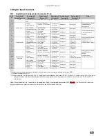
11.
Extended Parameters
11.1.
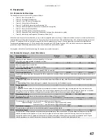
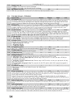
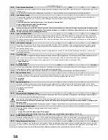
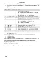
Parameter Group 2 - Extended parameters
Par
Parameter Name
Minimum
Maximum
Default
Units
P2-01
Preset Speed 1
-P1-01
P1-01
5.0
Hz / Rpm
Preset speed 1 is selected by configuring P1-13 to an option that permits logic selection, by using the user defined logic configuration
parameters in menu 9 (P9-21 to P9-23), or selection configured through the drive PLC function using the OptiTools Studio Suite PC
software.
P2-02
Preset Speed 2
-P1-01
P1-01
10.0
Hz / Rpm
Preset speed 2 is selected by configuring P1-13 to an option that permits logic selection, by using the user defined logic configuration
parameters in menu 9 (P9-21to P9-23), or selection configured through the drive PLC function using the OptiTools Studio Suite PC
software.
P2-03
Preset Speed 3
-P1-01
P1-01
25.0
Hz / Rpm
Preset speed 3 is selected using the user defined logic configuration parameters in menu 9 (P9-21 – P9-23), or selection configured
through the drive PLC function using the OptiTools Studio Suite PC software.
P2-04
Preset Speed 4
-P1-01
P1-01
P1-01
Hz / Rpm
Preset speed 4 is selected using the user defined logic configuration parameters in menu 9 (P9-21 – P9-23), or selection configured
through the drive PLC function using the OptiTools Studio Suite PC software.
P2-05
Preset Speed 5 (Clean Speed 1)
-P1-01
P1-01
0.0
Hz / Rpm
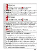
Preset speed 5 is automatically reference by the clean function when this function is enabled. See section 7.5, Pump clean function.
When clean function is disabled Preset speed 5 can be selected as per normal operation and is selected using the user defined logic
configuration parameters in menu 9 (P9-21 to P9-23), or selection configured through the drive PLC function using the OptiTools
Studio Suite PC software.
P2-06
Preset Speed 6 (Clean Speed 2)
-P1-01
P1-01
0.0
Hz / Rpm
Preset speed 6 is automatically reference by the clean function when this function is enabled. See section 7.5, Pump clean function.
When clean function is disabled Preset speed 6 can be selected as per normal operation and is selected using the user defined logic
configuration parameters in menu 6 (P9-21 to P9-23), or selection configured through the drive PLC function using the OptiTools
Studio Suite PC software.
P2-07
Preset Speed 7 (Boost Speed 1 / Pump Stir Speed)
-P1-01
P1-01
0.0
Hz / Rpm
Preset speed 7 is automatically referenced by the start / stop boost function, or the Pump Stir Function, when these functions are
enabled. See section 7.6, Pump Stir function and section 8, PID control applications. When HVAC functions are disabled Preset speed 7
can be selected as per normal operation and is selected using the user defined logic configuration parameters in menu 6 (P9-21 – P9-
23), or selection configured through the drive PLC function using the OptiTools Studio Suite PC software.
P2-08
Preset Speed 8 (Boost Speed 2)
-P1-01
P1-01
0.0
Hz / Rpm
Preset speed 8 is automatically reference by the start / stop boost function when this function is enabled. See section 8, PID control
applications. When boost function is disabled Preset speed 8 can be selected as per normal operation (and is selected using the user
defined logic configuration parameters in menu 6 (P9-21 to P9-23), or selection configured through the drive PLC function using the
OptiTools Studio Suite PC software.
P2-09
Skip Frequency Centre Point
P1-02
P1-01
0.0
Hz / Rpm
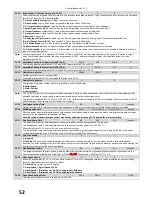
Defines the centre point of the skip frequency band. The width of the skip frequency band is defined by:
Lower limit = P2-09 - P2-10/2 : Upper limit = P2-09 + P2-10/2
All skip frequency bands defined for forward speeds are mirrored for negative speeds.
P2-10
Skip Frequency Band
0.0
P1-01
0.0
Units
Defines the width of the skip frequency band. The width of the skip frequency band is defined by:
Lower limit = P2-09 - P2-10/2: Upper limit = P2-09 + P2-10/2
All skip frequency bands defined for forward speeds are mirrored for negative speeds.
P2-11
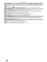
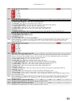
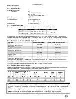
Analog Output 1 Function (Terminal 8)
0
11
8
-
Digital Output Mode. Logic 1 = +24V DC
0 : Drive Enabled (Running)
. Logic 1 when the drive is enabled (Running)
1: Drive Healthy
. Logic 1 When no Fault condition exists on the drive
2 : At Target Frequency (Speed)
. Logic 1 when the output frequency matches the set-point frequency
3 : Output Frequency > 0.0
. Logic 1 when the motor runs above zero speed
4 : Output Frequency >= Limit
. Logic 1 when the motor speed exceeds the adjustable limit
5 : Output Current >= Limit
. Logic 1 when the motor current exceeds the adjustable limit
6 : Reserved
. No Function
7
: Analog Input 2 Signal Level >= Limit
. Logic 1 when the signal applied to the Analog Input 2 exceeds the adjustable limit
Analog Output Mode (Format set in P2-12)
8 : Output Frequency (Motor Speed)
. 0 to P-01
9 : Output (Motor) Current
. 0 to 200% of P1-08
10 : Reserved
. No Function
11 : Output (Motor) Power
. 0 to 150% of drive rated power
Note:
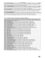
When using settings 4 – 7, parameters P2-16 and P2-17 are used to control the output behaviour. The output will switch to Logic 1
when the selected signal exceeds the value programmed in P2-16, and return to Logic 0 when the signal falls below the value
programmed in P2-17.
Содержание HVAC H2
Страница 1: ......
Страница 72: ...User Guide Revision 1 12 72 82 H2MAN BE_V1 11...

