19
4. SPECIAL APPLICATIONS
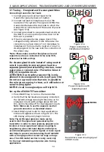
4.1 RCD-Protected Circuit Wire Tracing
Method 1
– Whenever possible use separate neutral connection as it is described in
Wire Tracing mode.
Method 2
– If separate neutral connection is not practical:
• De-energize the circuit.
• Connect a transmitter directivity to the wire as described in Wire Tracing method for
de-energized wires using separate ground connection (green test lead connected to the
Separate Ground instead of neutral wire).
• Perform tracing as described in the Wire Tracing or Breaker/Fuse modes.
4.2 Finding Breaks/Opens
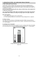
It is possible to pinpoint the exact location where the wire is broken using the Precision
Tracing mode, even if wire is located behind walls, floors or ceilings:
1. Make sure that wire is de-energized.
2. Use steps described in the Precision Tracing mode to connect the transmitter and
perform tracing. (see section 3.1).
3. For best results, ground all de-energized wires that run in parallel using special test lead.
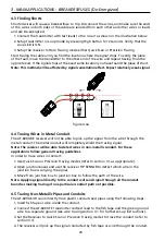
The tracing signal generated by the AT-6000-TE transmitter will be conducted along the wire
as long as there is continuity in the metal conductor. To find a fault, trace the wire until the
signal stops. To verify the fault’s location, move transmitter to the other end of the wire and
repeat tracing from the opposite end. If signal stops at the exact same location, you have
found the fault location.
Note: If the place of fault is not found, the open may be a high resistance break (partially
open circuit). Such a break would stop higher currents from flowing but will conduct
the tracing signal through the break. Such faults will not be detected until the wire is
completely open.
Figure 4.2a: Locating a break or open


