


Product overview
EL70x1
25
Version: 4.4
Resonance
At certain speeds, stepper motors run less smoothly. This phenomenon is particularly pronounced if the
motor runs without load. Under certain circumstances, it may even stop. This is caused by resonance. A
distinction can roughly be made between
• resonances in the lower frequency range up to approx. 250Hz; and
• resonances in the medium to upper frequency range.
Resonances in the medium to upper frequency range essentially result from electrical parameters such as
inductance of the motor winding and supply line capacity. They can be controlled relatively easily through
high pulsing of the control system.
Resonances in the lower range essentially result from the mechanical motor parameters. Apart from their
impact on smooth running, such resonances can lead to significant loss of torque, or even loss of step of the
motor, and are therefore particularly undesirable.
In principle, the stepper motor represents an oscillatory system (comparable to a mass/spring system),
consisting of the moving rotor with a moment of inertia and a magnetic field that creates a restoring force that
acts on the rotor. Moving and releasing the rotor creates a damped oscillation. If the control frequency
corresponds to the resonance frequency, the oscillation is amplified, so that in the worst case the rotor will
no longer follow the steps, but oscillate between two positions.
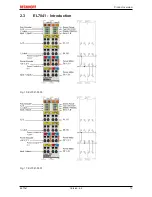
Due to their sine/cosine current profile, EL7031 and EL7041 EtherCAT Terminals are able to prevent this
effect in almost all standard motors. The rotor is not moved from step to step, so he no longer jumps to the
next position, but it moves through 64 intermediate steps, i.e. the rotor is gently moved from one step to the
next. The usual loss of torque at certain speeds is avoided, and operation can be optimized for the particular
application. This means that the lower speed range, where particularly high torque is available, can be fully
utilized.
Step angle
The step angle indicates the angle travelled during each step. Typical values are 3.6°, 1.8° and 0.9°. This
corresponds to 100, 200 and 400 steps per motor revolution. Together with the downstream transmission
ratio, this value is a measure for the positioning accuracy. For technical reasons, the step angle cannot be
reduced below a certain value. Positioning accuracy can only be improved further by mechanical means
(transmission). An elegant solution for improving positioning accuracy is the microstepping function offered
by the EL7031 and EL7041. It enables up to 64 intermediate steps. The smaller "artificial" step angle has a
further positive effect: The drive can be operated at higher speed, yet with the same precision. The
maximum speed is unchanged, despite the fact that the drive operates at the limit of mechanical resolution.
Specifying the stepper motor
1. Determine the required positioning accuracy and hence the step resolution. The first task is to deter-
mine the maximum resolution that can be achieved. The resolution can be increased via mechanical
gear reduction devices such as spindles, gearing or toothed racks. The 64-fold microstepping of the
stepper motor terminals also has to be taken into account.
2. Determine mass m and moment of inertia (J) of all parts to be moved
3. Calculate the acceleration resulting from the temporal requirements of the moved mass.
4. Calculate the forces from mass, moment of inertia, and the respective accelerations.
5. Convert the forces and velocities to the rotor axis, taking account of efficiencies, moments of friction
and mechanical parameters such as gear ratio. It is often best to start the calculation from the last
component, usually the load. Each further element transfers a force and velocity and leads to further
forces or torques due to friction. During positioning, the sum of all forces and torques acts on the mo-
tor shaft. The result is a velocity/torque curve that the motor has to provide.
6. Using the characteristic torque curve, select a motor that meets these minimum requirements. The
moment of inertia of the motor has to be added to the complete drive. Verify your selection. In order to
provide an adequate safety margin, the torque should be oversized by 20% to 30%. The optimization
is different if the acceleration is mainly required for the rotor inertia. In this case, the motor should be
as small as possible.
7. Test the motor under actual application conditions: Monitor the housing temperatures during continu-
ous operation. If the test results do not confirm the calculations, check the assumed parameters and
boundary conditions. It is important to also check side effects such as resonance, mechanical play,
settings for the maximum operation frequency and the ramp slope.
Содержание EL7031
Страница 1: ...Documentation EL70x1 Stepper Motor Terminals 4 4 2017 08 18 Version Date...
Страница 2: ......
Страница 6: ...Table of contents EL70x1 6 Version 4 4...
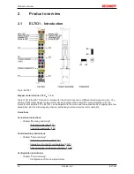
Страница 19: ...Product overview EL70x1 19 Version 4 4 2 3 EL7041 Introduction Fig 10 EL7041 0000 Fig 11 EL7041 0001...
Страница 21: ...Product overview EL70x1 21 Version 4 4 Application example Chapter Commissioning Application example 166...
Страница 48: ...Mounting and wiring EL70x1 48 Version 4 4 Fig 32 Other installation positions example 2...
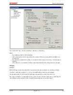
Страница 96: ...Commissioning EL70x1 96 Version 4 4 Fig 90 Incorrect driver settings for the Ethernet port...
Страница 107: ...Commissioning EL70x1 107 Version 4 4 Fig 109 EtherCAT terminal in the TwinCAT tree left TwinCAT 2 right TwinCAT 3...
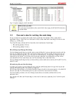
Страница 179: ...Commissioning EL70x1 179 Version 4 4 Index 7020 POS Outputs Ch 1...
Страница 203: ...Commissioning EL70x1 203 Version 4 4 Index 7020 POS Outputs Ch 1...


