Product overview
EL70x1
24
Version: 4.4
Typical stepper motor problems such as pronounced resonance are therefore a thing of the past.
Microstepping and associated set values ensure that rotor jerk is avoided. Also, the rotor no longer tends to
oscillate around each indexing position. Mechanical measures such as vibration dampers against resonance
or gear reduction for increasing precision are no longer required. This allows the burden from costs and
development effort to be lower.
The new stepper motor terminals also reduce development time on the control side. Both Bus Terminals can
be used just like standard EtherCAT Terminals in all common fieldbuses. Interface programming is therefore
no longer required. Start, stop or resonance frequencies are no longer an issue. For simple positioning tasks,
both EtherCAT Terminals can automatically position the drive, taking account of an acceleration ramp and
the maximum frequency.
Realization of more demanding positioning tasks
More demanding positioning tasks can be realized via the TwinCAT automation software from Beckhoff. Like
other axes, the two stepper motor terminals are integrated via the TwinCAT System Manager and can be
used like standard servo axes. Special stepper motor features, such as speed reduction in the event of large
following errors, are automatically taken into account via the
stepper motor axis
option. The effort for
changing from a servomotor to a stepper motor - and back - is no greater than changing from one fieldbus to
another one under TwinCAT.
The output stages of the stepper motor terminals have an overload protection in the form of an
overtemperature warning and switch-off. Together with short circuit detection, diagnostic data are accessible
in the process image of the controller. In addition, this status is displayed by the Bus Terminal LEDs, along
with other information. The output stage is switched on via an Enable-Bit. The motor current can be set and
reduced via a parameter value.
Optimum adaptation to the motor and the implementation of energy-saving features require minimum
programming effort. Since all data are set in the form of parameters in the CoE register, it is easily possible
to replace an EtherCAT Terminal or store certain parameters for transfer to the next project. It is therefore no
longer necessary to transfer certain potentiometer settings or to document DIP switch settings.
Stepper motor parameters
Torque
Refers to the maximum motor torque at different speeds. This parameter is usually represented by a
characteristic curve. Stepper motors have comparatively high torque in the lower speed range. In many
applications, this enables them to be used directly without gearing. Compared with other motors, stepper
motors can quite easily provide a holding moment of the same order of magnitude as the torque.
Speed
Stepper motors have low maximum speed, which is usually specified as a maximum step frequency.
Number of phases
Motors with 2 to 5 phases are common. The EL7031 and EL7041 EtherCAT Terminals support 2-phase
motors. 4-phase motors are basically 2-phase motors with separate winding ends. They can be connected
directly to the EtherCAT Terminal.
Nominal voltage, supply voltage and winding resistance
Under steady-state conditions, the rated current at the rated voltage depends on the winding resistance. This
voltage should not be confused with the supply voltage of the power output stage in the EtherCAT Terminal.
The EL7031 and EL7041 apply a controlled current to the motor winding. If the supply voltage falls below the
nominal voltage, the power output stage can no longer apply the full current, resulting in a loss of torque. It is
desirable to aim for systems with small winding resistance and high supply voltage in order to limit warming
and achieve high torque at high speeds.
Содержание EL7031
Страница 1: ...Documentation EL70x1 Stepper Motor Terminals 4 4 2017 08 18 Version Date...
Страница 2: ......
Страница 6: ...Table of contents EL70x1 6 Version 4 4...
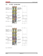
Страница 19: ...Product overview EL70x1 19 Version 4 4 2 3 EL7041 Introduction Fig 10 EL7041 0000 Fig 11 EL7041 0001...
Страница 21: ...Product overview EL70x1 21 Version 4 4 Application example Chapter Commissioning Application example 166...
Страница 48: ...Mounting and wiring EL70x1 48 Version 4 4 Fig 32 Other installation positions example 2...
Страница 96: ...Commissioning EL70x1 96 Version 4 4 Fig 90 Incorrect driver settings for the Ethernet port...
Страница 107: ...Commissioning EL70x1 107 Version 4 4 Fig 109 EtherCAT terminal in the TwinCAT tree left TwinCAT 2 right TwinCAT 3...
Страница 179: ...Commissioning EL70x1 179 Version 4 4 Index 7020 POS Outputs Ch 1...
Страница 203: ...Commissioning EL70x1 203 Version 4 4 Index 7020 POS Outputs Ch 1...


