Product description
EK1960
27
Version: 1.3.1
3.9
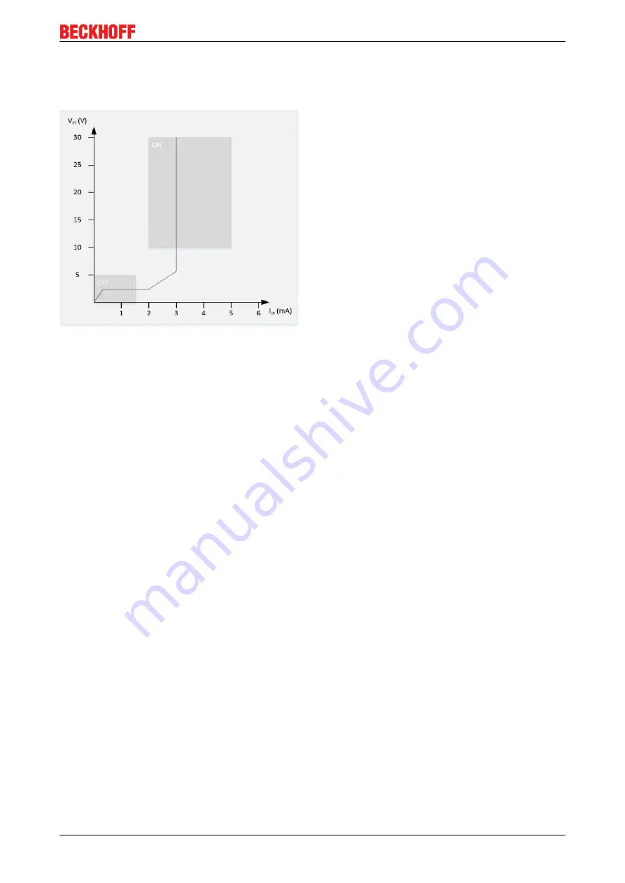
Characteristic curve of the inputs
The characteristic curve of the inputs of the EK1960 is similar to type 3 according to EN 61131-2.
Fig. 6: EK1960 input characteristic curve
3.10
Test pulses for the outputs
The output signals of each module of the EK1960 can be determined via the parameter
Diag TestPulse
Active
. The test pulses generated have a length of 400 µs, which is multiplied by the factor
MultiplierDiagTestPulse.
This factor should be set to at least 2 for outputs with no load or only a small load,
so that a test pulse length of 800 µs results. The frequency of the test pulses results from the processing of
the input and output modules and the cycle time of the internal logic. For example, if the logic has a cycle
time of 2 ms and a
ModuloDiagTestpulse
of 0, a typical time b results in accordance with the following
calculation.
For each output module the resulting time is:
module time = (4 cycles feedback test + (4 cycles diagnostic test * (ModuloDiagTes 1))) * internal
cycle time * 1.25 * 4 outputs = (4 + (4 * 1)) * 2 ms * 1.25 * 4 = 80 ms
For the relay module the resulting time is:
Relay module time = 100 * internal cycle time * 1.25
The input modules each require one cycle. This results in a total time b of:
b = 6 x module time + 1x relay module time + 10 x internal cycle time x 1.25 (for the input modules)
Inserting the values, this produces:
b= (6 * 80 ms) + (100 * 2 ms * 1.25) + (10 * 2 ms * 1.25) = 480 ms + 250 ms + 25 ms = 755 ms
The test pulse sequence is shown in the following table, where the time b typically elapses between a
channel test and a module switch test. The tests start over once they have been performed for all four
channels.
If the parameter
Diag TestPulse for Inputs active
is set in addition, all outputs of the module are switched on
and the test pulses shown here are similarly applied to the individual output channels. These signals can
then be used as clocked signals for the safe inputs. The module switch test is not performed in this operation
mode; instead, the four channels are tested directly in succession, leading to the time interval b between the
tests of the individual channels.
Содержание EK1960 Series
Страница 1: ...Operating Instructions for EK1960 TwinSAFE Compact Controller 1 3 1 2019 01 28 Version Date...
Страница 2: ......
Страница 6: ...Table of contents EK1960 6 Version 1 3 1...
Страница 58: ...Operation EK1960 58 Version 1 3 1 Fig 51 Safety parameters of the input modules...
Страница 102: ...Operation EK1960 102 Version 1 3 1 Fig 131 Group Status Online ERROR Fig 132 Group Status Online STOP...
Страница 140: ...Appendix EK1960 140 Version 1 3 1 5 2 Certificates...


