CANopen system overview
CXxxxx-M510/B510
17
Version: 1.0
The cycle time (SYNC rate) can be monitored (object 0x1006), so that if the SYNC fails the device
reacts in accordance with the definition in the device profile, and switches, for sample, its outputs into
the fault state.
The SYNC telegram is coupled with the link task, so that new input data are available with each task
start. If a synchronous PDO fails to materialize, this is detected and reported to the application.
•
Asynchronous:
The transmission types 254 + 255 are asynchronous or event-driven. In transmission type 254, the
event is specific to the manufacturer, whereas for type 255 it is defined in the device profile. In the
simplest case, the event is the change of an input value - this means that every change in the value is
transmitted. The asynchronous transmission type can be coupled with the event timer, thus also
providing input data when no event has just occurred. Once the set time has elapsed, this is interpreted
as an additional event, and the input data are sent.
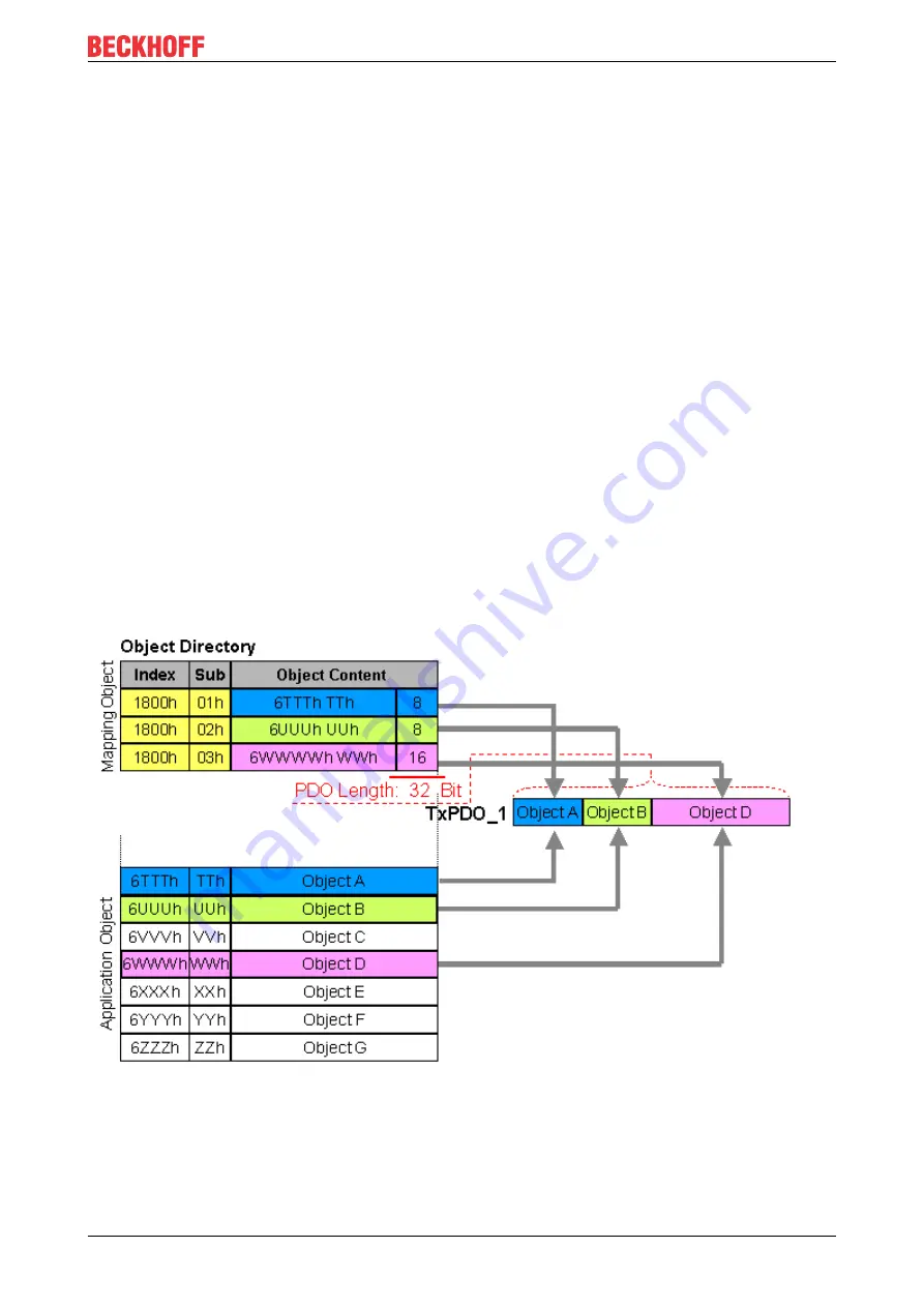
PDO Mapping
PDO mapping refers to mapping of the application objects (real time data) from the object directory to the
process data objects. The CANopen device profile provide a default mapping for every device type, and this
is appropriate for most applications. Thus the default mapping for digital I/O simply represents the inputs and
outputs in their physical sequence in the transmit and receive process data objects.
The default PDOs for drives contain 2 bytes each of a control and status word and a set or actual value for
the relevant axis.
The current mapping can be read by means of corresponding entries in the object directory. These are
known as the mapping tables. The first location in the mapping table (sub-index 0) contains the number of
mapped objects that are listed after it. The tables are located in the object directory at index 0x1600ff for the
RxPDOs and at 0x1A00ff for the TxPDOs.
Digital and analog input/output modules: Read out the I/O number
The current number of digital and analog inputs and outputs can be determined or verified by reading out the
corresponding application objects in the object directory:
Содержание CX-B510 Series
Страница 2: ......
Страница 36: ...TwinCAT tabs CXxxxx M510 B510 36 Version 1 0 4 3 CANopen slave 4 3 1 CAN node 1 3 7 11 13 5 6 2 12 8 9 4 10...
Страница 80: ......


