9190700990 Rev F
BE1-67N Functional Description
3-3
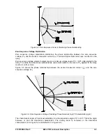
Figure 3-2. Zero Sequence Current Polarizing Phase Relationship
Zero Sequence Voltage Polarization
Zero sequence voltage polarization determines the phase relationship between the zero sequence
voltage (V
0
) and the sensed, measured current (I
op
). Third and higher harmonics have no effect on the
relay.
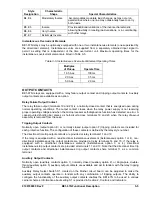
Zero sequence voltage element outputs require a minimum voltage level of V
0
= 0.75 volts applied to the
relay. To enable the directional, instantaneous overcurrent element, the level of V
0
applied to the relay
must be 4 volts or more.
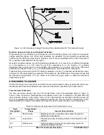
Figure 3-3 shows the phase relationship between the sensed measured current (I
op
) and the zero
sequence voltage (V
0
).
Figure 3-3. Zero Sequence Voltage Polarizing Phase Relationship (0
°
Characteristic Angle)
The characteristic angle is front-panel selectable for a line impedance angle of 0
°
or 60
°
. This is the angle
between V
0
and the directional characteristic. The closing band is centered on the directional
characteristic (V
0
in Figure 3-3 and shifted 60
°
in Figure 3-4).
Содержание BE1-67N
Страница 2: ......
Страница 6: ...iv BE1 67N Introduction 9190700990 Rev F This page intentionally left blank...
Страница 8: ...vi BE1 67N Introduction 9190700990 Rev F This page intentionally left blank...
Страница 10: ...ii BE1 67N General Information 9190700990 Rev F This page intentionally left blank...
Страница 18: ...1 8 BE1 67N General Information 9190700990 Rev F This page intentionally left blank...
Страница 20: ...ii BE1 67N Controls and Indicators 9190700990 Rev F This page intentionally left blank...
Страница 26: ...ii BE1 67N Functional Description 9190700990 Rev F This page intentionally left blank...
Страница 34: ...ii BE1 67N Installation 9190700990 Rev F This page intentionally left blank...
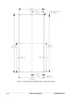
Страница 36: ...4 2 BE1 67N Installation 9190700990 Rev F Figure 4 1 Panel Cutting and Drilling Diagram Semi Flush Mounting...
Страница 37: ...9190700990 Rev F BE1 67N Installation 4 3 Figure 4 2 Panel Drilling Diagram Projection Mounting...
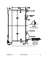
Страница 38: ...4 4 BE1 67N Installation 9190700990 Rev F P0002 14 08 10 01 Figure 4 3 Cover Dimensions Front View...
Страница 39: ...9190700990 Rev F BE1 67N Installation 4 5 Figure 4 4 Case Dimensions Rear View...
Страница 43: ...9190700990 Rev F BE1 67N Installation 4 9 Figure 4 7 Typical Internal Connections...
Страница 46: ...4 12 BE1 67N Installation 9190700990 Rev F This page intentionally left blank...
Страница 48: ...ii BE1 67N Testing 9190700990 Rev F This page intentionally left blank...
Страница 58: ...ii BE1 67N Characteristic Curves 9190700990 Rev F This page intentionally left blank...
Страница 60: ...A 2 BE1 67N Characteristic Curves 9190700990 Rev F Figure A 1 Timing Type B1 Short Inverse Switch Position 3...
Страница 61: ...9190700990 Rev F BE1 67N Characteristic Curves A 3 Figure A 2 Timing Type B2 Long Inverse Switch Position 1...
Страница 62: ...A 4 BE1 67N Characteristic Curves 9190700990 Rev F Figure A 3 Timing Type B3 Definite Time Switch Position 5...
Страница 63: ...9190700990 Rev F BE1 67N Characteristic Curves A 5 Figure A 4 Timing Type B4 Moderate Inverse Switch Position 2...
Страница 64: ...A 6 BE1 67N Characteristic Curves 9190700990 Rev F Figure A 5 Timing Type B5 Inverse Switch Position 4...
Страница 65: ...9190700990 Rev F BE1 67N Characteristic Curves A 7 Figure A 6 Timing Type B6 Very Inverse Switch Position 6...
Страница 68: ...A 10 BE1 67N Characteristic Curves 9190700990 Rev F Figure A 9 Timing Type E4 BS 132 Inverse Switch Position 9...
Страница 69: ...9190700990 Rev F BE1 67N Characteristic Curves A 11 Figure A 10 Timing Type E5 BS 142 Inverse Switch Position A...
Страница 72: ...A 14 BE1 67N Characteristic Curves 9190700990 Rev F This page intentionally left blank...
Страница 74: ...B 2 BE1 67N Polar Graph Forms 9190700990 Rev F This page intentionally left blank...


