9190700990 Rev F
BE1-67N Functional Description
3-5
Style
Designation
Characteristic
Shape Special
Characteristics
B4, E4
Moderately Inverse
Accommodates moderate load changes, as may occur on
parallel lines where one line may occasionally have to carry
both loads.
B5, E5
Inverse
B6, E6
Very Inverse
B7, E7
Extremely Inverse
Provide additional variations of the inverse characteristic,
allowing flexibility in meeting load variations, or in coordinating
with other relays.
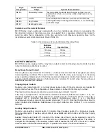
Instantaneous Overcurrent Elements
BE1-67N relays may be optionally equipped with one or two instantaneous elements (one supervised by
the directional element). Instantaneous units are supplied from a separately obtained input signal to
permit a setting that is independent of the time overcurrent unit. Maximum operating times for the
instantaneous overcurrent element are listed in Table 3-5.
Table 3-5. Instantaneous Overcurrent Element Operating Times
Multiples
of Pickup
Operate Time
1.05 Aac
100 ms
2.0 Aac
35 ms
5.0 Aac
20 ms
OUTPUT CONTACTS
BE1-67N relays are equipped with a relay failure output contact and tripping output contacts. Auxiliary
output contacts are available as an option.
Relay Failure Output Contact
The relay failure output (terminals 19 and 20) is a normally-closed contact that is energized open during
normal operating conditions. The output contact closes when the relay power supply is not receiving
proper operating voltage and when the microprocessor self-diagnostics function has detected an error. A
case-mounted shorting bar places a short-circuit across terminals 19 and 20 when the relay draw-out
assembly is removed from the case.
Tripping Output Contacts
Normally open (output option E) or normally closed (output option F) tripping contacts are included for
each protective function. The configuration of these contacts is defined by the relay style number.
The directional time trip output contacts are provided at relay terminals 11 and 12.
If the relay is equipped with a non-directional instantaneous element (instantaneous option 1 or 4), non-
directional instantaneous trip output contacts are provided at relay terminals 14 and 15. If the relay is
equipped with a directional instantaneous element (instantaneous option 3 or 4), directional
instantaneous trip output contacts are provided at terminals 11 and 13. Note that the directional time trip
output contacts and directional instantaneous trip output contacts share terminal 11 as a common
terminal.
Auxiliary Output Contacts
Normally open (auxiliary contacts option 1), normally closed (auxiliary option 2), or single-pole, double-
throw (auxiliary option 5) auxiliary output contacts are available and act in tandem with the relay tripping
functions.
Auxiliary Relay Select Switch S1, located on the Mother circuit board, can be adjusted to make the
auxiliary output contacts operate in tandem with any combination of tripping outputs. The ability to
configure the functionality of the auxiliary output contacts enables the BE1-67N to be used in various
carrier schemes. Information about setting S1 is provided in Section 2,
Controls and Indicators
.
Содержание BE1-67N
Страница 2: ......
Страница 6: ...iv BE1 67N Introduction 9190700990 Rev F This page intentionally left blank...
Страница 8: ...vi BE1 67N Introduction 9190700990 Rev F This page intentionally left blank...
Страница 10: ...ii BE1 67N General Information 9190700990 Rev F This page intentionally left blank...
Страница 18: ...1 8 BE1 67N General Information 9190700990 Rev F This page intentionally left blank...
Страница 20: ...ii BE1 67N Controls and Indicators 9190700990 Rev F This page intentionally left blank...
Страница 26: ...ii BE1 67N Functional Description 9190700990 Rev F This page intentionally left blank...
Страница 34: ...ii BE1 67N Installation 9190700990 Rev F This page intentionally left blank...
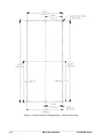
Страница 36: ...4 2 BE1 67N Installation 9190700990 Rev F Figure 4 1 Panel Cutting and Drilling Diagram Semi Flush Mounting...
Страница 37: ...9190700990 Rev F BE1 67N Installation 4 3 Figure 4 2 Panel Drilling Diagram Projection Mounting...
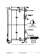
Страница 38: ...4 4 BE1 67N Installation 9190700990 Rev F P0002 14 08 10 01 Figure 4 3 Cover Dimensions Front View...
Страница 39: ...9190700990 Rev F BE1 67N Installation 4 5 Figure 4 4 Case Dimensions Rear View...
Страница 43: ...9190700990 Rev F BE1 67N Installation 4 9 Figure 4 7 Typical Internal Connections...
Страница 46: ...4 12 BE1 67N Installation 9190700990 Rev F This page intentionally left blank...
Страница 48: ...ii BE1 67N Testing 9190700990 Rev F This page intentionally left blank...
Страница 58: ...ii BE1 67N Characteristic Curves 9190700990 Rev F This page intentionally left blank...
Страница 60: ...A 2 BE1 67N Characteristic Curves 9190700990 Rev F Figure A 1 Timing Type B1 Short Inverse Switch Position 3...
Страница 61: ...9190700990 Rev F BE1 67N Characteristic Curves A 3 Figure A 2 Timing Type B2 Long Inverse Switch Position 1...
Страница 62: ...A 4 BE1 67N Characteristic Curves 9190700990 Rev F Figure A 3 Timing Type B3 Definite Time Switch Position 5...
Страница 63: ...9190700990 Rev F BE1 67N Characteristic Curves A 5 Figure A 4 Timing Type B4 Moderate Inverse Switch Position 2...
Страница 64: ...A 6 BE1 67N Characteristic Curves 9190700990 Rev F Figure A 5 Timing Type B5 Inverse Switch Position 4...
Страница 65: ...9190700990 Rev F BE1 67N Characteristic Curves A 7 Figure A 6 Timing Type B6 Very Inverse Switch Position 6...
Страница 68: ...A 10 BE1 67N Characteristic Curves 9190700990 Rev F Figure A 9 Timing Type E4 BS 132 Inverse Switch Position 9...
Страница 69: ...9190700990 Rev F BE1 67N Characteristic Curves A 11 Figure A 10 Timing Type E5 BS 142 Inverse Switch Position A...
Страница 72: ...A 14 BE1 67N Characteristic Curves 9190700990 Rev F This page intentionally left blank...
Страница 74: ...B 2 BE1 67N Polar Graph Forms 9190700990 Rev F This page intentionally left blank...

