9190700990 Rev F
BE1-67N Controls and Indicators
2-3
ANALOG AND DIGITAL CIRCUIT BOARD CONTROLS
Front panel HMI components are illustrated in Figure 2-2 and described in Table 2-2. The locators and
descriptions of Table 2-1 correspond to the locators shown in Figure 2-2.
Figure 2-2. Analog and Digital Circuit Board Controls
Table 2-2. Analog and Digital Circuit Board Controls
Locator Description
A
Polarizing Source Select Switch (S3).
This assembly located on the Analog circuit board,
consists of two switches. The left-hand switch enables zero-sequence voltage polarization
and the right-hand switch enables zero-sequence current polarization. The up position of
the switch (as shown) selects the function.
B
Normal/Test Switch (S1).
This switch is used only during factory calibration and should
remain in the Normal position.
C
Time Overcurrent Characteristic Curve Selector Switch (S6).
This switch selects the
characteristic curve to be used for the application. See Appendix A,
Characteristic Curves
for the curves available.
Содержание BE1-67N
Страница 2: ......
Страница 6: ...iv BE1 67N Introduction 9190700990 Rev F This page intentionally left blank...
Страница 8: ...vi BE1 67N Introduction 9190700990 Rev F This page intentionally left blank...
Страница 10: ...ii BE1 67N General Information 9190700990 Rev F This page intentionally left blank...
Страница 18: ...1 8 BE1 67N General Information 9190700990 Rev F This page intentionally left blank...
Страница 20: ...ii BE1 67N Controls and Indicators 9190700990 Rev F This page intentionally left blank...
Страница 26: ...ii BE1 67N Functional Description 9190700990 Rev F This page intentionally left blank...
Страница 34: ...ii BE1 67N Installation 9190700990 Rev F This page intentionally left blank...
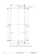
Страница 36: ...4 2 BE1 67N Installation 9190700990 Rev F Figure 4 1 Panel Cutting and Drilling Diagram Semi Flush Mounting...
Страница 37: ...9190700990 Rev F BE1 67N Installation 4 3 Figure 4 2 Panel Drilling Diagram Projection Mounting...
Страница 38: ...4 4 BE1 67N Installation 9190700990 Rev F P0002 14 08 10 01 Figure 4 3 Cover Dimensions Front View...
Страница 39: ...9190700990 Rev F BE1 67N Installation 4 5 Figure 4 4 Case Dimensions Rear View...
Страница 43: ...9190700990 Rev F BE1 67N Installation 4 9 Figure 4 7 Typical Internal Connections...
Страница 46: ...4 12 BE1 67N Installation 9190700990 Rev F This page intentionally left blank...
Страница 48: ...ii BE1 67N Testing 9190700990 Rev F This page intentionally left blank...
Страница 58: ...ii BE1 67N Characteristic Curves 9190700990 Rev F This page intentionally left blank...
Страница 60: ...A 2 BE1 67N Characteristic Curves 9190700990 Rev F Figure A 1 Timing Type B1 Short Inverse Switch Position 3...
Страница 61: ...9190700990 Rev F BE1 67N Characteristic Curves A 3 Figure A 2 Timing Type B2 Long Inverse Switch Position 1...
Страница 62: ...A 4 BE1 67N Characteristic Curves 9190700990 Rev F Figure A 3 Timing Type B3 Definite Time Switch Position 5...
Страница 63: ...9190700990 Rev F BE1 67N Characteristic Curves A 5 Figure A 4 Timing Type B4 Moderate Inverse Switch Position 2...
Страница 64: ...A 6 BE1 67N Characteristic Curves 9190700990 Rev F Figure A 5 Timing Type B5 Inverse Switch Position 4...
Страница 65: ...9190700990 Rev F BE1 67N Characteristic Curves A 7 Figure A 6 Timing Type B6 Very Inverse Switch Position 6...
Страница 68: ...A 10 BE1 67N Characteristic Curves 9190700990 Rev F Figure A 9 Timing Type E4 BS 132 Inverse Switch Position 9...
Страница 69: ...9190700990 Rev F BE1 67N Characteristic Curves A 11 Figure A 10 Timing Type E5 BS 142 Inverse Switch Position A...
Страница 72: ...A 14 BE1 67N Characteristic Curves 9190700990 Rev F This page intentionally left blank...
Страница 74: ...B 2 BE1 67N Polar Graph Forms 9190700990 Rev F This page intentionally left blank...


