2-3
Installation Verification
Operator Manual
920512-768
❑
Electrical supply for unit is as specified on equipment drawing.
❑
Electrical connections between washer and mechanical core are
as specified in
S
ECTION
3
of
Uncrating/Installation Instructions
(P920512-767).
❑
Verify electrical boxes. Ensure no foreign objects inside electri-
cal boxes. Also check for any unconnected wires.
❑
Verify all electrical connections are plugged in and/or con-
nected.
❑
Building hot water line supplies water to unit as specified on
equipment drawing.
❑
If Drain Discharge Cool Down System with Cold Water Injec-
tion is present,
building cold water line supplies water to unit as
specified on equipment drawing.
❑
If Drain Discharge Cool Down System with Chilled Water and
pH Neutralizing System is present,
building cold water line
supplies water to unit as specified on equipment drawing.
❑
Building steam line provides steam to unit as specified on equip-
ment drawing.
❑
Building condensate return line is connected to washer as spec-
ified on equipment drawing.
❑
Building waste line is connected to washer as specified on
equipment drawing.
❑
Piping connections between washer and mechanical core are as
specified in
S
ECTION
3
of
Uncrating/Installation Instructions
(P920512-767).
❑
Building ventilation system is connected to washer as specified
on equipment drawing.
❑
Building air line supplies air to unit as specified on equipment
drawing.
❑
Air line connections between washer and mechanical core are
as specified in
S
ECTION
3
of
Uncrating/Installation Instructions
(P920512-767).
❑
Verify all clamps and unions on washer and mechanical core.
Tighten if necessary.
❑
All pneumatic connections and switches are properly installed,
adjusted and connected.
❑
If Drying System option is present,
drying system connections
between washer and mechanical core are as specified in
S
EC
-
TION
3
of
Uncrating/Installation Instructions
(P920512-767).
❑
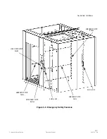
Springs for emergency stop cables (on top of washer) are cor-
rectly installed on microswitch.
❑
Switch(es) for EMERGENCY STOP pushbutton, located on con-
trol access panel on load side for single door units or on both
load and unload side, if double-door unit, are correctly installed.

