• For operation on RS-232, connect RS-232(TXD) to (+),
RS-232(RXD) to GND) to RTN (see Figure 28 below).
6. For connection to a PC to interface with
AuroraView
software, you may use the supplied 704-688 cable
(RS-232 w/ SUB-D-9 connector to tinned leads). Wire
the cable as follows:
Color Code
Aurora H2O terminal
White
Tx
+
Red
Rc
Green
Ground
RTN
The as-shipped default configuration is as follows:
BAUD rate:
115,200
Parity:
Even
Network ID:
1 for port 1, 2 for port 2
7. Use a separate wiring conduit run for any 4-20mA
pressure transmitter input. This input is used when a live
input pressure reading for the main process pressure
is desired, to determine an equivalent dew point by
the
Aurora H2O
analyzer. Wire the 4-20mA pressure
transmitter to the pressure transmitter terminal block
(see Figure 29 below). The
Aurora H2O
supplies 24VDC for
use with a loop-powered, 2-wire pressure transmitter.
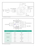
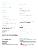
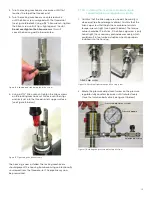
Figure 28: (Left)Input/output connections
Figure 29: (Right) Pressure transmitter connections
IMPORTANT
Use of an external pressure transmitter is not covered by
the
Aurora H2O
hazardous area certifications.
The external pressure transmitter should be suitably rated
for the area classification. Its associated wiring should be
done in accordance with local codes and regulations, and
suitably rated for the area classification.
8. If the
Aurora H2O
has been supplied with an optional
electrical heater, there are two possible configurations:
USA/CAN or EU. Connect the AC power using a separate
conduit from the power for the
Aurora H2O
analyzer.
The heater is equipped with a thermostat preset to
25°C (77°F) nominal. Use 12-18 AWG (3.3 - 0.82 mm
2
)
wires. The heater terminals are located within a
junction box (item 15 in Figure 2 on page 3 or Figure 3
9. Lastly, the
Aurora H2O
analyzer requires a connection
to ground from the electronics explosion-proof/flame-
proof enclosure. As shown in Figure 30 below, there are
two external ground connections available for the user
(on the left and right hand sides of the enclosure). Wire
this connection to earth ground, local to the
Aurora H2O
analyzer installation site.
Figure 30: Earth ground connection
2.9 Specific conditions of use
Before operating your
Aurora
system, be sure the
following conditions are met:
• In the event of repair or replacement of any
components, the manufacturer, Panametrics
infrastructure sensing, shall be contacted for information
on the controlled materials and dimensions of the
flameproof characteristics of the
Aurora H2O
moisture analyzer.
• The laser head assembly of the
Aurora H2O
moisture
analyzer shall be inside a tool secured enclosure with
IP20 or better to ensure the factory installed laser head
assembly bolts are inaccessible from the outside.
• Consult the manufacturer for genuine replacement
flange fasteners. 5/16 inch-24 x 1-1/4 inch 18-8 stainless
steel socket head cap bolts or better with a minimum
tensile strength of 70,000 psi are acceptable alternatives.
• To reduce the potential of an electrostatic charging
hazard, do not rub painted aluminum parts with a
dry cloth.
19
Содержание Panametrics Aurora H2O
Страница 2: ...ii...
Страница 4: ...no content intended for this page proceed to next page iv...
Страница 20: ...no content intended for this page 10...
Страница 32: ...no content intended for this page 22...
Страница 65: ...2 AuroraView boots up and displays a screen similar to Figure 55 below Figure 55 AuroraView main screen 55...
Страница 71: ...Figure 74 Exporting a simplified image Figure 75 Selecting enhanced metafile 61...
Страница 80: ...no content intended for this page 70...


