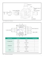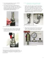
3. Refer to Figure 18 below and position the membrane
end of the probe above the installed housing. Slowly
lower the probe into the housing. Avoid membrane
contact with the upper section of the housing.
Do not
apply downward force.
The probe should slide easily into
the housing. Lower the probe only enough to thread the
insertion nut one complete turn of thread engagement.
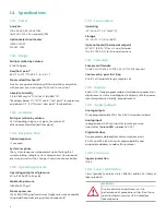
4. Thread the insertion nut down by hand, lowering the
probe until the insertion washer pins slide to the bottom
of the first vertical slot (see Figure 19 below).
NOTE:
The threaded nut on the housing ensures that
if all other safety procedures are disregarded, it is
mechanically impossible to remove the probe.
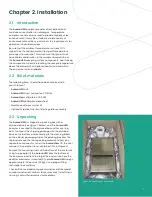
5. Rotate the probe counterclockwise until the pins
are to the far right in the horizontal slot. At this point,
the probe is sealed against the housing interior
Membrane
Housing
Membrane
spring
guard
Insertion
nut
Insertion
washer
Housing
First
vertical
slot
Second
vertical
slot
Figure 18: Installing the probe
Insertion
nut
Insertion
washer
Pin
Housing
Figure 19: Threading the insertion nut
wall. The pins will be in the middle of the second
vertical slot (see Figure 20 below).
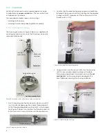
6. Loosen the insertion nut until it is above the top of the
second vertical slot (see Figure 21 below). The probe
should not rise to the top of the second vertical slot.
If the probe rises in the slot, the foot valve o-ring may
have been damaged or attacked by the process.
NOTE:
The threaded nut on the housing ensures that if all
other safety procedures are disregarded, it is mechanically
impossible to remove the probe. Perform the next step
regardless of the status of the foot valve o-ring.
7. Tighten the insertion nut by hand until it is against the
insertion washer again. Using a wrench, tighten the
insertion nut against the insertion washer so that the
pins are at the bottom the second vertical slot (see
Figure 22 below). At this point the foot valve opens and
the insertion process is complete.
Figure 20: Rotating the probe
Figure 21: Loosening the
insertion nut
Figure 22: Tightening the
insertion nut
16
16
Содержание Panametrics Aurora H2O
Страница 2: ...ii...
Страница 4: ...no content intended for this page proceed to next page iv...
Страница 20: ...no content intended for this page 10...
Страница 32: ...no content intended for this page 22...
Страница 65: ...2 AuroraView boots up and displays a screen similar to Figure 55 below Figure 55 AuroraView main screen 55...
Страница 71: ...Figure 74 Exporting a simplified image Figure 75 Selecting enhanced metafile 61...
Страница 80: ...no content intended for this page 70...


