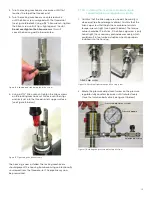
3. Run the AC power connections to the power terminal
block shown in Figure 26 below. It is recommended to
use 12-18 AWG (3.3 - 0.82 mm
2
) power wiring.
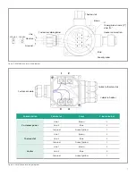
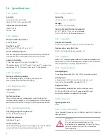
Figure 26: Power terminal block
4. Use wiring conduit runs, separate from the
Aurora H2O
main power, for all I/O (input/output) leads. Wire up
to three 4-20mA outputs to the terminals labeled A, B,
and C. The three analog outputs A, B and C (0-20mA or
4-20mA) are internally powered by the
Aurora H2O
. Use
shielded 18-22 AWG (0.82-0.33 mm
2
) twisted pairwire,
and ground the shield at one end only. Wire up digital
communications to port 1 and/or port 2 as labeled.
5. Either digital port may be configured for RS-232 or
RS-485. Port 1 is designated as “service.” For operation
on RS-485, 2 wire, half-duplex bus, attach the RS-485(+)
to (+), and modbus-IDA specifications, a third, common
conductor must also interconnect all the devices of the
bus. Attach the common conductor to RTN.
NOTE:
For an RS-485 Multi-drop network, a terminating
resistor must be installed across the
Aurora H2O
RS-485
terminals, or an internal terminating resistor can be applied.
See below.
• When using the
Aurora H2O
in RS-485 mode, and to
prevent signal reflections on the high-speed RS-485
connections, it is recommended that the far end of the
RS-485 lines be terminated properly. The termination
can be accomplished in one of two ways:
– Connect 120
Ω
, ¼ W leaded resistors across the
+ and – terminals of ports 1 and 2 (both ports or
whichever one will be in use)
– Using long-nose pliers, move jumpers J15 and J16
from pins 2 and 3 (default setting from factory) to
pins 1 and 2 (see Figure 27 on page 28). J16 is the
termination for port 1 and J15 is the termination for
port 2. It is also recommended that basic ESD
precautions such as grounded wrist straps be
used for this procedure.
Multi-drop RS-485:
For multiple
Aurora H2O
units connected in daisy-chain
fashion to the RS485 interface, it is important that the
farthest unit away from the transmitting device be the only
unit incorporating any termination (see Figure 27 below).
All other units must have jumpers J15 and J16 in positions
2 and 3 (default setting from the factory). For more details
on RS-485 wiring or operation, refer to TIA/EIA-485-A
specification.
NOTE:
The internal terminations MUST be in the default
(unterminated) position for operation in RS-232 mode.
Figure 27: RS-485 mode termination - install jumpers at J15 and J16, pins 1 and 2
18
18
Содержание Panametrics Aurora H2O
Страница 2: ...ii...
Страница 4: ...no content intended for this page proceed to next page iv...
Страница 20: ...no content intended for this page 10...
Страница 32: ...no content intended for this page 22...
Страница 65: ...2 AuroraView boots up and displays a screen similar to Figure 55 below Figure 55 AuroraView main screen 55...
Страница 71: ...Figure 74 Exporting a simplified image Figure 75 Selecting enhanced metafile 61...
Страница 80: ...no content intended for this page 70...


