background image

Copyright 2013 Baker Hughes Company.

36 | DPI


620G Instruction Manual–English

Chapter


3.


Calibrator

3.5  Utility Options

For each function only one utility may be active at any time. Not all source and measure functions 

have associated utilities.
For all utility options the 

 button resets the additional readings provided by the selected utility.

The utilities available are:

Max/Min/Avg

Leak Test (see Section


5.7)

Switch Test

Relief Valve Test

3.5.1  Max/Min/Avg

The 

 Max/Min/Avg utility is only available with measure functions.

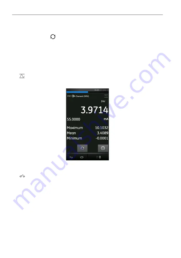
When this utility is selected, the real-time minimum, maximum, and average values of the 

measured signal is displayed in addition to the live measured reading.

Figure


3

-

13: Max/Min/Avg Example

3.5.2  Switch Test

The 

 Switch Test is available with measure or source functions.

The additional readings displayed show signal values (measure or source) when the instrument 

detects a switch opening and closing. The difference between the two values is displayed as the 

hysteresis value for the switch. This utility can be used with Ramp Automation, where the rising 

Содержание Druck DPI 620 Genii

Страница 1: ...Druck com DPI 620 Genii Advanced Modular Calibrator Instruction Manual...

Страница 2: ......

Страница 3: ...by the equipment may be impaired This publication contains operating and safety instructions that must be followed to make sure of safe operation and to maintain the equipment in a safe condition The...

Страница 4: ...ive Druck is an active participant in Europe s Waste Electrical and Electronic Equipment WEEE take back initiative directive 2012 19 EU The equipment that you bought has required the extraction and us...

Страница 5: ...alth dc Direct current DD Device Description DPI Digital Pressure Instrument DUT Device Under Test etc And so on e g For example FF FOUNDATION Fieldbus FS Full Scale ft Foot g Gauge H2O Water Hz Hertz...

Страница 6: ...Copyright 2013 Baker Hughes Company iv DPI 620G Instruction Manual English TC Thermocouple USB Universal Serial Bus V Volts C Degrees Celsius F Degrees Fahrenheit Abbreviation Description...

Страница 7: ...16 1 Return Goods Material Procedure 7 1 16 2 Safety Precautions 7 1 16 3 Important Notice 7 1 16 4 For More Information Contact 7 1 17 Packaging for Storage or Transportation 7 1 18 Environment 7 2...

Страница 8: ...etector RTD 45 4 10 Measure or Simulate a Thermocouple TC 47 4 11 Switch Test 48 5 Pressure Tasks 51 5 1 Introduction 51 5 2 Module Carrier and PM 620 PM 620T Pressure Modules 52 5 2 1 Assembly Instru...

Страница 9: ...Device Configuration 84 9 5 7 Create a New HART Configuration 87 9 5 8 Open a HART Offline Configuration 88 9 5 9 File Management 89 9 6 HART Online 89 9 6 1 HART SDC Application 89 9 6 2 HART SDC Da...

Страница 10: ...canning for Devices 118 11 8 Context Sensitive Menu 119 11 9 Troubleshooting Connection Problems 120 11 10 Profibus Application Communication 120 11 10 1 Device Focus View 120 11 10 2 Block Navigation...

Страница 11: ...12 9 Procedures CH1 True Ohms Measure 142 12 10 Procedures CH1 Resistance Source 143 12 11 Procedures CH1 TC mV Measure or Source 144 12 12 Procedures CH1 Cold Junction TC Method and CJ Measure 145 1...

Страница 12: ...Copyright 2013 Baker Hughes Company x DPI 620G Instruction Manual English...

Страница 13: ...C probe Set of six test leads Quick start guide 1 3 Optional Items The items that follow are optional items which can be used with the Druck DPI 620 Genii Optional Item Description Pressure Module Car...

Страница 14: ...nel operating and maintaining the equipment are correctly trained and qualified Before operating or using the equipment read and obey all sections including all WARNINGS and CAUTIONS given in the Safe...

Страница 15: ...manufacturer the protection provided by the equipment may be impaired Do not use the instrument in locations with explosive gas vapor or dust There is a risk of an explosion WARNING The DC input to th...

Страница 16: ...release of pressure isolate and bleed the system before disconnecting a pressure connection To prevent a dangerous release of pressure make sure that all the related pipes hoses and equipment have the...

Страница 17: ...screws Figure 1 3 Installing the Battery 1 12 Charging the Battery 1 Connect the DC power supply into the 5V DC connection on the side of the unit see Figure 1 4 2 The unit can be on or off when char...

Страница 18: ...a weak detergent solution Table 1 2 Battery Charging Times Charging Connection Charge Time DC Power Supply 6 5 hours External Battery Charger 6 5 hours Option Description SWITCH OFF Initiates full pow...

Страница 19: ...HH references and precautions to be taken when handling 1 16 3 Important Notice Do not use unauthorized sources to service this equipment as this will affect the warranty and may not guarantee further...

Страница 20: ...Copyright 2013 Baker Hughes Company 8 DPI 620G Instruction Manual English Chapter 1 Introduction...

Страница 21: ...i can be used in the following modes 1 Calibrator with independent functions on each of six channels This includes the following capabilities for each function a Data logging b Documenting 2 HART Comm...

Страница 22: ...on Note HART FOUNDATION Fieldbus and Profibus PA are optional items Table 2 1 Dashboard Icons Icon Function Advanced Calibrator Data Logging Documenting Files Applications Help Settings Blue Status LE...

Страница 23: ...e modified Figure 2 2 Settings 2 2 1 1 Brightness Intensity To adjust the brightness intensity of the screen press and drag the slider button left or right to decrease or increase respectively 2 2 1 2...

Страница 24: ...red International Temperature Scale ITS standard to utilize on the device The two options available are IPTS 68 and ITS 90 Note Default selection is ITS 90 2 2 1 8 Enable Hold Button Select the tick b...

Страница 25: ...ed in this menu and provides the following options Figure 2 4 Help Menu Figure 2 5 Example Connection Help Diagram Help Option Description MANUAL View user manual document on the DPI 620 Genii screen...

Страница 26: ...ashboard by pressing the Status icon The Status menu options available are listed as shown in Figure 2 6 Figure 2 6 Status Menu 2 2 3 1 Alarm State An Alarm Status is indicated with a red LED on the A...

Страница 27: ...he red LED shows alarms such as Date Time not set Calibration overdue etc Figure 2 8 Alarm State Selecting the displayed alarm will clear the indication until the next device restart 2 2 4 Software Bu...

Страница 28: ...ailable on the DPI 620 Genii are listed below Application DK420 Operating System DK419 Boot Loader DK418 HART Driver Processor Application DK417 HART Boot Loader DK416 SDC625 Application DK421 HART De...

Страница 29: ...dication of power source i e charging or battery powered 2 2 4 4 Memory Status Displays the portion of the device memory used and that which is available The memory information covers the following In...

Страница 30: ...et connection is available Word Viewer Allows access to Microsoft Word format documents e g doc txt rtf which can be viewed and edited Excel Viewer Allows access to Microsoft Excel format e g xls csv...

Страница 31: ...hould only be accessed by competent users to perform calibrations on the DPI 620 Genii See Section 12 and update its software components See Section 2 2 6 1 2 2 6 1 Upgrading the Software Download the...

Страница 32: ...System upgrade is required it is recommended to upgrade the Operating System before the Application software a Copy the AMC application folder into the root of the USB flash memory device b Insert th...

Страница 33: ...Software Upgrade menu select the HART Device Library DK401 5 Follow the on screen instructions 6 Upgrade will take approximately 30 minutes b Method 2 Using a PC and USB cable 1 Download the HART Lib...

Страница 34: ...evices Menu 2 2 7 1 USB Client Port The DPI 620 Genii USB port can be configured into one of three modes Figure 2 16 USB Client Port Configuration Menu USB Client Port Option Description Storage Devic...

Страница 35: ...Genii user settings can be accessed and modified by selecting the Files icon Figure 2 17 Files Menu 2 2 8 1 Save Settings Saves all the current user settings on the device 2 2 8 2 Recall Settings Prev...

Страница 36: ...e back to factory default settings Figure 2 19 Clear Settings Confirmation 2 2 8 4 Delete Settings Erases selected existing saved settings files 2 2 8 5 Export Favourites Exports Favorites that have b...

Страница 37: ...rt Favourites Imports Favorites files that have been previously saved on a USB flash drive into the device A USB flash drive containing the correct Favorites setup folder must be detected successfully...

Страница 38: ...Copyright 2013 Baker Hughes Company 26 DPI 620G Instruction Manual English Chapter 2 Instrument Operation...

Страница 39: ...is a total of six separate channels listed as follows Electrical Channels CH1 and CH2 Pressure via PM 620 PM 620T and MC 620G Channels P1 and P2 External Sensor USB supports sensors such as TERPS IDO...

Страница 40: ...tion Manual English Chapter 3 Calibrator Figure 3 2 displays an expanded view of the selected channel CH2 and minimizes the remaining channels CH1 and P1 Figure 3 2 Calibrator Window Expanded View on...

Страница 41: ...l Function 4 Sensor Type 5 Utility Icon 6 Measurement Reading 7 Measurement Unit 8 Channel Settings 9 Hold Pause Readings 10 Home or Dashboard 11 Back 12 Additional Measurement Data 13 Sensor Full sca...

Страница 42: ...Pressure Tasks Select Pressure Tasks from the Task Menu to display a list of pre defined pressure related tasks The Pressure Task option will only be available if a pressure sensor is detected such a...

Страница 43: ...sks Select the required function by selecting either the appropriate text or diagram The DPI 620 Genii will set the functions and return to the Calibrator screen 3 3 3 Saving Tasks At any point within...

Страница 44: ...Task Refer to Section 3 3 5 1 Selecting FAVOURITES from the Task Menu displays all saved and copied tasks and allows the required one to be selected 2 Select the required function by tapping on eithe...

Страница 45: ...ion Channel Description CH1 Set up CH1 by entering the channel settings menu CH2 Set up CH2 by entering the channel settings menu P1 is used for pressure measurements with pressure module connected on...

Страница 46: ...hannel type e g Electrical channels CH1 and CH2 will not have any pressure related functions and Pressure channels P1 and P2 will not have any electrical functions UNITS selects the type of measuremen...

Страница 47: ...Calibrator mode 3 4 1 Automation Source Functions have additional settings available which include the following options Nudge allows the source value to be incremented by a defined step size value Sp...

Страница 48: ...t 3 5 1 Max Min Avg The Max Min Avg utility is only available with measure functions When this utility is selected the real time minimum maximum and average values of the measured signal is displayed...

Страница 49: ...3 Relief Valve The Relief Valve utility is only available with measure functions This utility tests circuits or mechanisms that have a cut out response when an input reaches a defined threshold value...

Страница 50: ...available depend on the function and include Option Description Tare Used to set a temporary value for zero This makes an adjustment to all subsequent readings on the display Alarm Used to indicate wh...

Страница 51: ...istance measure simulate RTD measure simulate Pulses measure source Observed source allows a value to be manually entered e g the reading of a connected voltmeter 4 1 Measure or Source Current Figure...

Страница 52: ...option CH1 Measure Voltage or Millivolts V or mV 2 Complete the electrical connections and continue with the measure operation 4 3 Measure AC Voltage CH1 20 V RMS Maximum Figure 4 3 shows CH1 set up t...

Страница 53: ...Volts with AC Probe Range 300 V RMS 1 Set the applicable channel option for the AC Probe 2 Complete the electrical connections Red V Hz connector Black COM connector Then continue with the measure ope...

Страница 54: ...op power supply Loop power has three possible settings 1 None current only 2 24 V 3 28 V Figure 4 6 Current Loop Supply Options Figure 4 7 and Figure 4 8 show CH2 set up to measure 55 mA or source 0 t...

Страница 55: ...e A Measure Frequency on CH1 Range 0 to 50 kHz 1 Set applicable channel options CH1 Source Frequency Hz or other unit 2 Complete the electrical connections 3 Default channel settings Range 0 to 50 kHz...

Страница 56: ...ource Frequency CH1 Range 0 to 50 kHz 1 Set the applicable channel options 2 Complete the electrical connections 3 Default channel settings Range 0 to 50 kHz Waveform Square Amplitude 5 0 V If necessa...

Страница 57: ...nly applies when Sine and Triangle waveforms are selected 4 9 Measure or Simulate a Resistance Temperature Detector RTD Figure 4 12 Figure 4 13 and Figure 4 14 show CH1 set up to measure an RTD A 4 wi...

Страница 58: ...connections 3 If necessary change the RTD Type default is PT100 4 SETTINGS RTD TYPE The MEASURE OHMS MODE can also be selected as Standard or True Ohms Note To measure or simulate resistance select t...

Страница 59: ...ge 270 to 1372 C Figure 4 17 K Type Thermocouple Source CH1 Range 270 to 1372 C Note To measure or simulate TC millivolts set the TC mV function 1 Set the applicable channel options 2 Complete the ele...

Страница 60: ...hannel for the switch connections CH1 P1 P2 and IDOS TERPS functions use the CH2 switch connections CH2 functions use the CH1 switch connections Note If there is a measure or source function on the sw...

Страница 61: ...cycle 7 Use to stop the Ramp cycle 8 If necessary supply the output values in the opposite direction until the switch changes condition again 9 The display will show the following a Value for switch O...

Страница 62: ...Copyright 2013 Baker Hughes Company 50 DPI 620G Instruction Manual English Chapter 4 Electrical Tasks...

Страница 63: ...use of the module carrier MC 620G and applicable pressure modules PM 620 or PM 620T or with the use of an external pressure sensor Figure 5 1 MC 620G with PM 620 Pressure Modules To make a fully integ...

Страница 64: ...ully integrated pressure indicator measuring pneumatic or hydraulic pressure CAUTION To prevent damage to the PM 620 or PM 620T module only use it within the specified pressure limit on the label 1 Pr...

Страница 65: ...620T module and the calibrator is established 5 3 Pressure Connections The pressure ports for external equipment use Quick fit pressure adaptors See Figure 5 6 Figure 5 6 Quick Fit Pressure Adaptor 1...

Страница 66: ...aptor to the MC 620G carrier and hand tighten Figure 5 7 Pressure Connections When the pressure indicator assembly is complete use the menus to set up the necessary operations Refer to Section 3 3 and...

Страница 67: ...ressure Tasks Select the required function by selecting on either the appropriate text or diagram The DPI 620 Genii will set the functions and return to the Calibrator screen Pressure Functions can al...

Страница 68: ...0 IDOS USB to the IDOS module 2 Push the type A end of USB cable into the USB socket on the instrument and the type B end into the adaptor IO620 IDOS USB 3 Power on the instrument 4 When the IDOS symb...

Страница 69: ...d with the DPI 620 Genii using USB communication to enhance the calibrator functionality Before using a TERPS module please refer to the user manual K0473 Druck TERPS 8000 8100 8200 8300 Series Note T...

Страница 70: ...for a TERPS module or for a MC 620G PM 620 PM 620T assembly After channel set up is complete continue with the pressure operation Figure 5 14 TERPS Pressure Measurement on External Sensor Channel 5 7...

Страница 71: ...pressure sensor must be correctly installed 5 8 Set the Pressure Module to Zero SETTINGS ZERO ZERO Use this option to write a new zero pressure value to the pressure module in use The sensor zero adj...

Страница 72: ...Copyright 2013 Baker Hughes Company 60 DPI 620G Instruction Manual English Chapter 5 Pressure Tasks...

Страница 73: ...The RTD INTERFACE is optionally supplied with a field rewireable M12 connector for users to connect their own wire ended RTDs This is accessory part number IO RTD M12CON The pin numbering is printed o...

Страница 74: ...e Task menu in the Calibrator application Select the RTD INTERFACE option in the list of Functions on the External sensor channel settings menu Figure 6 3 RTD INTERFACE Channel Settings 6 2 Utilities...

Страница 75: ...READING MODE Allows the temperature measurement to be displayed as a Temperature C or F b Resistance Ohms UNITS Allows change of units depending on the Reading Mode selected RTD PROFILES Based on the...

Страница 76: ...20G Instruction Manual English Chapter 6 Temperature Tasks RTD Interface 6 4 User Profiles There are up to ten customizable User Profiles which can be edited to suit the requirement Figure 6 6 RTD Pro...

Страница 77: ...can be reviewed or analyzed This chapter describes how to use the Data Logging function to log data to a file Figure 7 1 Data Logging In Data Logging mode the display data from all active channels is...

Страница 78: ...ime the button is pressed b Periodic logs one data point at a set time interval PERIOD This option is used to set the time interval for periodic data logging To start Data Logging Mode 1 Select approp...

Страница 79: ...viewed by selecting Recall from the Data logging menu Figure 7 3 Data Log File Menu To view a summary of the Data log file 1 Tap on FILENAME to display the list of data files 2 Select the file to be...

Страница 80: ...w a data file on as a chart 1 Tap the Filename button to display the list of data files 2 Select the file to be displayed 3 Select VIEW CHART Figure 7 6 Data Log Chart Press the Zoom In button to magn...

Страница 81: ...to another device or computer to be processed externally DELETE Erase data log files 7 4 1 Transfer Data may be transferred using any of the following USB Flash Drive Selected files are written in th...

Страница 82: ...lect All button then press the Delete button to delete all the selected files 7 4 3 Data Format The data files are produced in a Comma Separated Variable csv format See Figure 7 9 This allows the data...

Страница 83: ...021 10 00 15 10 841 mA Current 10 4681 mA Current 24V 4 10 Aug 2021 10 00 20 13 519 mA Current 13 0331 mA Current 24V 5 10 Aug 2021 10 00 25 16 213 mA Current 15 8164 mA Current 24V 6 10 Aug 2021 10 0...

Страница 84: ...Copyright 2013 Baker Hughes Company 72 DPI 620G Instruction Manual English Chapter 7 Data Logging...

Страница 85: ...n also be used to calculate the transfer characteristic between three points in the signal path and may be calibrated at the same time as in the example that follows When calibrating a process transmi...

Страница 86: ...annel type to Reference 3 All other channel settings for this Reference channel will no longer be available All other active channels are automatically set as Input channel s 8 1 3 Define Input Channe...

Страница 87: ...the ideal transfer characteristic A tolerance limit test icon Pass within tolerance test limit Fail outside tolerance test limit To check the full range of the device 1 Step the Reference signal valu...

Страница 88: ...PI 620 Genii calibrator A communications symbol will be displayed at the bottom of the screen 7 Select RUN PROCEDURE from the Documenting Menu or by selecting the 4Sight2 icon from the Dashboard 8 In...

Страница 89: ...ts damping The DPI 620 Genii can be used to communicate with other HART field devices As a Primary Master the DPI 620 Genii starts and controls all communications The field device slave uses each comm...

Страница 90: ...PI 620 Genii supplies the loop power and a 250 HART resistor Figure 9 1 HART Device Connection with Loop Power 9 3 2 External Loop Power In the example that follows there is an external power supply M...

Страница 91: ...gure 9 3 HART Communicator Network Connection CH2 function is set to None The HART function is enabled on the HART channel with the 250 resistor is set to Off 9 3 4 Use of Test Connections To use the...

Страница 92: ...n The HART Offline feature sits alongside the existing HART application to provide extended offline capabilities All devices available in HART library are supported Typical operations include the foll...

Страница 93: ...ns Figure 9 7 HART Device Polling Options Select Use address 0 only to search for any device found on address 0 only Select Find First Device to search from 0 to 63 and use the first device found Sele...

Страница 94: ...d use the first device found Select Search range to use a specified address range to select from a range of devices at poll addresses within that range 3 When the poll scheme type has been selected pr...

Страница 95: ...vice will be displayed 4 Edit the device details where required 9 5 4 Change Device To change the currently connected device to another device select the CHANGE DEVICE option from the HART menu Press...

Страница 96: ...ed Figure 9 10 HART Offline Device Summary 9 5 6 Open Device Configuration Select the OPEN DEVICE CONFIG from the HART menu to view and modify the device configuration The device PV URV and LRV parame...

Страница 97: ...typically contains calibration related parameters BASIC SETUP covering only a few basic device data such as device TAG Units Damping DETAILED SETUP covers more parameters associated with the sensor si...

Страница 98: ...TO DEVICE writes the current configuration file including the new changes made to the HART device When this option is selected choose from the following additional upload mode options All Parameter S...

Страница 99: ...u will open Figure 9 15 HART Offline Create New HART Configuration Select the following sections in order 1 MANUFACTURER name of Manufacturer 2 DEVICE TYPE model or device name based on manufacturer s...

Страница 100: ...the Offline Configuration menu of the device Figure 9 17 HART Offline Configuration File Name Entry 9 5 8 Open a HART Offline Configuration Having created an offline configuration either connected or...

Страница 101: ...ine HART devices can also be connected to the DPI 620 Genii in HART ONLINE mode which allows detailed configuration To set up a device connection ONLINE select the HART ONLINE button This launches a D...

Страница 102: ...active The icon functions are described below Icon Name Description OPEN NEW CONNECTION Requires HART SDC application to Exit and restart from Dashboard PREFERENCES Selection of Search Options Poll Ad...

Страница 103: ...e 9 23 HART Poll Preferences Figure 9 24 HART Device Status DEVICE COMMUNICATIONS ON Indicator showing active communication DEVICE COMMUNICATIONS STARTING Indicator showing communication is starting D...

Страница 104: ...with a V or E icon can be edited Edit variables as follows 1 Select the variable 2 If a selection window is opened select the variable or select Edit button Figure 9 25 HART Write Variable Selection...

Страница 105: ...ing on the device in use Methods may include the following Self test Loop test Sensor trim D A trim To execute any of the above listed methods 1 Select the required folder in the SDC data structure Fi...

Страница 106: ...ns 5 Some methods require input from the DPI 620 Genii instrument channels A drop down menu displays the channels as follows CH1 CH2 P1 P2 IDOS 6 On completion the procedure will return to the HART ap...

Страница 107: ...is set to Measure Current 24V this can be used to supply the reference meter value 4 Read the CH2 value and enter this in the meter value text box using the keypad Figure 9 29 Enter Calibration Point...

Страница 108: ...onfiguration file to be edited Upload Config to Device This enables a previously saved HART configuration file to be uploaded to a connected device Fault Possible Cause Action Failed to find device Po...

Страница 109: ...ed copied or cloned on a PC 9 10 4 Delete HART Configuration Deletes the HART configuration file from the DPI 620 Genii 9 10 5 Delete All HART Configuration Files From the main offline menu all saved...

Страница 110: ...Copyright 2013 Baker Hughes Company 98 DPI 620G Instruction Manual English Chapter 9 HART Operations...

Страница 111: ...FOUNDATION Fieldbus is started by selecting the FIELDBUS button from the Dashboard FOUNDATION Fieldbus can also be selected from within the CALIBRATOR function by selecting the Fieldbus option on the...

Страница 112: ...n for FOUNDATION Fieldbus devices over a FOUNDATION Fieldbus H1 connection Icon Name Description OPEN CONNECTION Only available when awaiting an open connection When navigating devices Open Connection...

Страница 113: ...in the selected range will appear in the bus tree window list All scanned devices are shown as a bold icon with an associated tag Previous scan results are indicated in gray Figure 10 5 Device Scan V...

Страница 114: ...0 6 Re scan 10 5 Context Sensitive Menu Context sensitive menus are available for each device in the Device Scan menu by tapping and holding on the PD tag device name Figure 10 7 Context Sensitive Dev...

Страница 115: ...ce with the specific user manual supplied with the field device and segment coupler power supply 2 The loop is not suffering from interference due to an unstable voltage supply from the segment power...

Страница 116: ...10 8 The Navigation Menu Tree This is the overview of the entire loaded block of the device this is not the entire field device only one aspect of it showing all the menus available according to the...

Страница 117: ...are shown in gray The target mode can be changed with a momentary touch on the block header Figure 10 11 shows an example where target mode is Auto but actual mode is Out of Service OOS 10 9 Functiona...

Страница 118: ...y online offline is signified by the communication progress bar in the bottom right of the screen 10 9 1 Displaying Parameter Help The yellow triangle in the corner of the Variable Description area in...

Страница 119: ...n the toolbar become active Figure 10 15 Edit Value Individual updates can be reverted by selecting Revert Value from the context menu Accessed by a tap and hold action on the variable description Not...

Страница 120: ...ns in the online device In complex devices with multiple menus this allows the user to navigate a device without a manual greatly simplifying the online experience even with an unfamiliar device The s...

Страница 121: ...it relates to is displayed Figure 10 19 Found TRIM Methods 5 Function Finder will then display the Function Group concerned in the device view with all searched variables highlighted in yellow Refer...

Страница 122: ...iable Description area Refer to Figure 10 22 Note Only Parameters that return a value can be added to the Export List Note A Maximum of six parameters can be added to the Export List Items on List can...

Страница 123: ...ted parameter will be displayed in the FOUNDATION Fieldbus channel window Figure 10 23 Displaying Primary Value 10 13 Fieldbus Application My Block My Block allows the user to create menus of commonly...

Страница 124: ...ters to My Block 10 14 Application Settings Application settings are access from the FOUNDATION Fieldbus toolbar by selecting Settings 10 14 1 Device Library The library tab shows the Device Descripti...

Страница 125: ...ation start up for new Device Descriptions Note this configuration option requires a network path to the Internet After installation the default setting is checked Confirm Device Commits If checked br...

Страница 126: ...Copyright 2013 Baker Hughes Company 114 DPI 620G Instruction Manual English Chapter 10 FOUNDATION Fieldbus...

Страница 127: ...terminators and a power supply This allows the connection of the DPI 620 Genii to Already existing networks where the power supply and termination are already present Standalone Profibus PA devices A...

Страница 128: ...he DPI 620 Genii to a PROFIBUS PA network Figure 11 2 Example Connection Diagram Profibus 2 Select the PROFIBUS channel so that it is in its expanded view Figure 11 3 Calibrator Profibus Channel 3 Sel...

Страница 129: ...SB setting is in Storage mode See Section 2 2 7 11 6 Profibus Toolbar On entering the Profibus application the toolbar is displayed Icons that are not currently active are grayed out Figure 11 5 Profi...

Страница 130: ...es found will appear in the tree window list All scanned devices are shown as a bold icon with an associated descriptor and ABORT Abort Update of parameters reverts to previous values refer to Section...

Страница 131: ...o the Search bar to look for a specific device in the discovered scan list 4 Selecting a device in the search results and selecting OK will initiate connection to the Device Focus view Refer to Sectio...

Страница 132: ...segment coupler power supply 2 The loop is not suffering from interference due to an unstable voltage supply from the segment power supply and or electrical interference 3 The required termination is...

Страница 133: ...refer to Section 11 13 2 function blocks may or may not be visible in the Device Focus view Icon Block Name Description Resource Devices only have one resource block Specifies the general characteris...

Страница 134: ...g the desired block with a single key press will open the Navigation Tree for that block Refer to Section 11 10 2 11 10 2 Block Navigation Tree Once a block is selected the navigation tree will be sho...

Страница 135: ...n Tree DPI620 11 10 3 Block Header Bar The block header bar indicates the target and actual mode of the block Figure 11 13 Profibus Block Header Bar The highlighted text indicates the actual mode of t...

Страница 136: ...Profibus Folder Parameters The left hand side hosts the Variable Description Area and access to the context based adjustment functions The right hand side with light background hosts the Variable Edi...

Страница 137: ...ing Display Help will show the help attributes Figure 11 18 Profibus Parameter Help 11 10 6 Refreshing Data When a refresh is in progress the variable description goes gray and in the right hand side...

Страница 138: ...and cancel icons in the toolbar become active Figure 11 22 Profibus Edited Parameter Individual updates can be reverted by selecting Revert Value from the context menu Accessed by a touch and hold ge...

Страница 139: ...s to be displayed in the Communications channel window The selected variables are defined by the Export List menu Refer to Section 11 10 2 Parameters are added to the Export List using the context men...

Страница 140: ...gure 11 26 Displaying Primary Value 11 13 Profibus Application Settings Application settings are access from the Profibus toolbar by selecting the Settings button for the following options 11 13 1 Dev...

Страница 141: ...of results select the parameter that is required Note that the variable name and the folder it relates to is displayed Option Description Poll header every Sets the refresh rate for the device parame...

Страница 142: ...130 DPI 620G Instruction Manual English Chapter 11 Profibus PA 4 Function Finder will then display the Folder Variables concerned in the Device view with all searched variables highlighted in yellow F...

Страница 143: ...CH2 Current mA calibrator For accuracy see Table 12 2 Current mA calibrator For accuracy see Table 12 3 Voltage CH1 Voltage calibrator For accuracy see Table 12 5 Voltage calibrator For accuracy see T...

Страница 144: ...PM 620 Range 25 mbar 0 36 psi Module Carrier MC 620G or Pressure Base PV 62XG Pressure Calibrator Total uncertainty of 0 015 reading or better Pressure PM 620 Range 25 mbar 0 36 psi Module Carrier MC...

Страница 145: ...g measure functions for this range any adjustment will affect the corresponding source function calibration The source function must therefore be re calibrated after adjusting the measure function 1 C...

Страница 146: ...procedure as follows 1 Connect the applicable calibration equipment Refer to Table 12 1 2 Let the equipment get to a stable temperature minimum 5 minutes since the last power on 3 CH1 has only one ra...

Страница 147: ...adjustment will affect the corresponding source function calibration The source function must therefore be re calibrated after adjusting the measure function Do the procedure as follows 1 Connect the...

Страница 148: ...via the Calibrator Task Menu b Apply the input values that are applicable to the calibration mV 2000 1000 200 100 0 short circuit mV 0 100 200 1000 2000 Volts V 30 21 20 10 5 0 short circuit Volts V 0...

Страница 149: ...ion Zero and FS for the applicable range a mV source ranges 2000 mV b Volts source ranges 20 V Figure 12 5 Calibration Voltage Source CH1 Range 20 V 4 Check the calibration is correct a Select the app...

Страница 150: ...Let the equipment get to a stable temperature minimum 5 minutes since the last power on 3 Set up the equipment as follows a Signal generator Output 10 V Unipolar Square wave Frequency 990 Hz b DPI 62...

Страница 151: ...e point frequency calibration 5 Check the calibration is correct 12 6 2 Frequency Calibration Source Function Do the procedure as follows 1 Connect the applicable calibration equipment Refer to Table...

Страница 152: ...0 Genii Input trigger level 5 V Units Hz or kHz as specified in Table 12 8 or Table 12 9 2 Frequency source calibration check a Frequency meter Gate time 1 second b DPI 620 Genii Units Hz or kHz as sp...

Страница 153: ...follows Source frequency 0 for DC output Waveform Square b Apply the amplitude values that are applicable to the calibration Refer to Table 12 10 c Check the error is within limits Refer to Table 12 1...

Страница 154: ...is correct a Select the applicable Resistance measure function via the Calibrator Task Menu b Make a 4 wire connection to the applicable standard resistor and measure the value c Check the error is w...

Страница 155: ...o do a two point resistance source calibration for each of the following ranges Range 0 400 Range 400 2000 Range 2k 4k Figure 12 9 Calibration Resistance Source CH1 Range 2000 to 4000 4 Check the cali...

Страница 156: ...inals using the recommended calibration equipment Refer to Table 12 1 Do the procedure as follows 1 Connect the applicable calibration equipment Refer to Table 12 1 2 Let the equipment get to a stable...

Страница 157: ...1 Cold Junction TC Method Do the procedure as follows 1 Connect the applicable calibration equipment Refer to Table 12 1 2 Set the reference unit temperature 0 C 3 Let the equipment get to a stable t...

Страница 158: ...play shows Sampling complete set the correct Cal Value CJ Cal Value in step 6 9 Check the calibration is correct a Select the TC measure function via the Calibrator Task Menu b Check the equipment giv...

Страница 159: ...ration gauge sensor FS Zero and FS for gauge sensors Zero and FS for absolute sensors Note If software version requires a three point calibration for an absolute sensor use points at 0 50 and FS or th...

Страница 160: ...d for calibration 12 15 Procedures TERPS USB Refer to the user manual K0473 Druck TERPS Refer to Section 12 14 for procedure When the calibration is complete the instrument automatically sets a new ca...

Страница 161: ...t the applicable RTD Interface measure function via the Calibrator Task Menu b Apply the following values FS 0 25 50 75 100 c Check the error is within limits Refer to Table 12 19 Table 12 19 RTD Resi...

Страница 162: ...Copyright 2013 Baker Hughes Company 150 DPI 620G Instruction Manual English Chapter 12 Calibration Procedures...

Страница 163: ...wered to guarantee measurement specification Note The case of the DPI 620 Genii is not suitable for prolonged exposure to UV Note The DPI 620 Genii is not suitable for permanent installation in an out...

Страница 164: ...Copyright 2013 Baker Hughes Company 152 DPI 620G Instruction Manual English Chapter 13 General Specification...

Страница 165: ......

Страница 166: ...Company This material contains one or more registered trademarks of Baker Hughes Company and its subsidiaries in one or more countries All third party product and company names are trademarks of thei...

Отзывы: