


104
Appendix A Using the LCD Panel
This appendix discusses the process of using the LCD panel to set up the Rainier 3G Plus.
The LCD panel allows for the control of some functions of the Rainier 3G Plus including; output
resolution and signal adjustment, user logo, audio (headphone and HDMI), cascade, HDMI output
source, preset file, color correction, clock, window display parameters, alarm, aspect ratio adjustment,
safe area and operational status reports.
The LCD panel consists of 5 buttons:
Go to next selection (up arrow button)
Go to previous selection (down arrow button)
Move to left of present cursor position (left arrow button)
Move to right of present cursor position (right arrow button)
Enter the next level of a menu, or select the currently highlighted item.
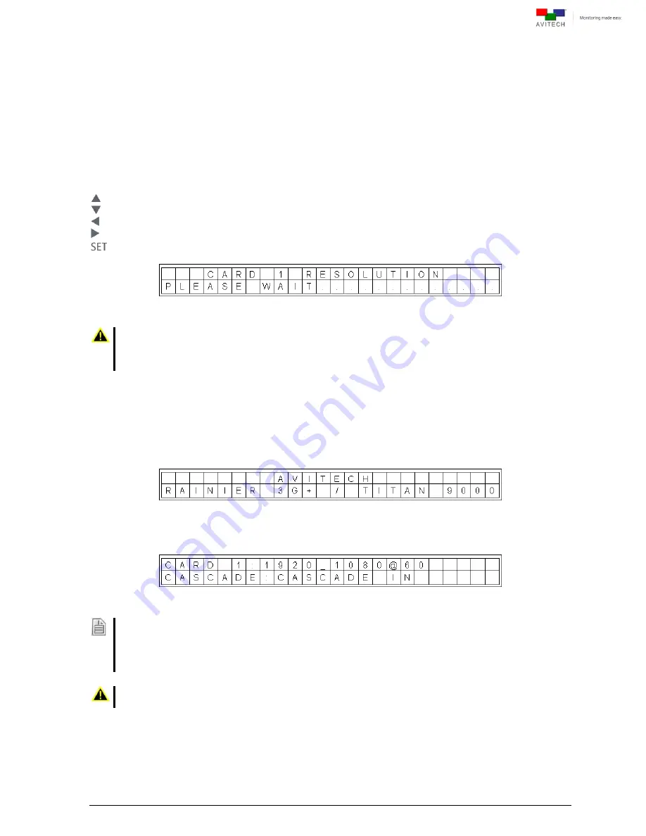
Figure A-1
LCD Panel: Busy State
1.
When the busy state “
PLEASE WAIT . . . .
” message is displayed on the LCD panel (see sample
screen above),
DO NOT
disconnect or connect any signal cables.
2. Also,
DO NOT
change any of the incoming signal’s display resolutions while the Rainier 3G Plus is in
the busy state.
A.1 Welcome Screen
Upon starting up the LCD panel, the welcome screen is shown for a few seconds.
Figure A-2
LCD Panel: Welcome Screen
Then the following default screen is displayed.
Figure A-3
LCD Panel: Default Initial Screen
This screen displays the card
’s default settings.
1. First line (video): Display the first card
’s current video output settings.
2. Second line (cascade method):
The default cascade method for Rainier 3G Plus
– (1 Card) is
Cascade In
.
The default cascade method for Rainier 3G Plus
– (Q card) is
Off
.
Settings made through the LCD panel will be saved automatically upon turning off power to the Rainier 3G
Plus.
Содержание Rainier 3G Plus
Страница 1: ...User Manual Rainier 3G Plus Multiviewing experience taken to the next level Revision 1 0 0 May 2014 ...
Страница 99: ...93 Image Layout and Alarm Trigger Change Audio meter scale ...
Страница 111: ...105 Figure A 4 LCD Panel Menu Tree ...
Страница 129: ...123 Sample illustration 3 Figure B 3 Audio Output From Chassis ID 2 Card ID 4 Image 3 Plus Chassis ID 1 Headset ...


