background image


38


4. Basic Setup Using the In-System GUI


The in-system GUI contains a collective of settings for the Pacific MS. It provides routing control for 
video (including embedded audio) and USB mouse/keyboard. Additionally, it offers a real-time 
monitoring interface – two fully customizable preview windows for source preview and output 
confirmation. Other advanced configurations include grouping of workstations, custom labeling, and 
remote layout adjustment for multiviewer outputs.   
 
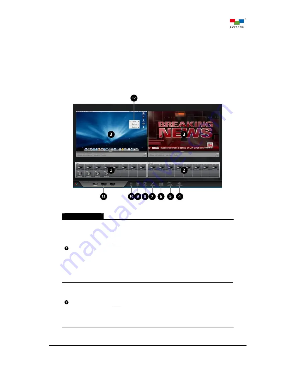
The following table gives an overview of all the in-system GUI’s components and their function 
descriptions in brief.  


Figure 4-1

 In-system GUI Component 


In-System GUI 


  Input Control 

Bar 

Automatic sensing of installed input cards and port status: 


Input Ports


  Pacific MS-2: input port from (1) up to (12)  

  Pacific MS-3: input port from (1) up to (20) 

Note: Input signal icons vary in accordance with different types of 
input cards/ports (HDMI, BNC, or RJ-45 ports).   


Color indicators 

(3 independent indicators per input port) 

  Glows blue when detecting video signal presence   

  Glows green when detecting embedded audio signal presence 

and the input port has been previewed on the in-system GUI 

  Glows amber when detecting USB connection with the source 

computer (for bypassing mouse/keyboard control) 

  Output Control 

Bar 

Automatic sensing of installed output cards and port status 


Output ports


  Pacific MS-2: output port from (1) up to (8) 

  Pacific MS-3: output port from (1) up to (16) 

Note: Output signal icons vary in accordance with different types of 
output cards (HDMI or RJ-45 ports).


Color indicator 


  Glows blue when detecting monitor presence  

Содержание Pacific MS-2

Страница 1: ...User Manual Pacific MS HDMI DVI SDI and HDBaseT KVM Matrix Switcher Revision 1 0 0 February 2016 ...

Страница 2: ...t us in making improvements to this user manual we welcome any comments and constructive criticism Please email us at sales avitechvideo com WARNING Do not attempt to disassemble the Pacific MS Doing so may void the warranty There are no serviceable parts inside Please refer all servicing to qualified personnel TRADEMARKS All brand and product names are trademarks or registered trademarks of their...

Страница 3: ...led Card 16 2 3 Connecting Video Sources to Pacific MS Input Cards 17 2 4 Connecting Monitors to Pacific MS Output Cards 18 2 5 Connecting Pacific MS to Source Computers USB Ports 19 2 6 Connecting Pacific MS to Sources Audio Ports Microphone Function 20 2 7 Connecting Monitor for In System GUI and Local Computer Management 20 2 8 Basic Setup for Video Switching and Routing 21 2 9 Basic Setup for ...

Страница 4: ...58 5 5 2 Functions 58 5 5 3 Hot keys 59 5 6 SOB QPW Remote Mode 59 6 Multi Monitor Workstation Configuration and Operation 60 6 1 Configuration of Multi Monitor Workstation 60 6 2 Multi Monitor Workstation Operation 71 Appendix A Using the Surfer Feature 74 A 1 Surfer Feature on Uniform Dual Layout SOB HPW 74 A 2 Surfer Feature on Uniform Quad Layout SOB QPW 75 A 3 Surfer Feature on Non adjoining ...

Страница 5: ...y Period Avitech makes its best offer to repair a product that is outside the warranty period provided the product has not reached its end of life EOL The minimum charge for such repair excluding shipping and handling is 200 US dollars AVITECH INTERNATIONAL CORPORATION 15377 NE 90th Street Redmond WA 98052 USA TOLL FREE 1 877 AVITECH PHONE 1 425 885 3863 FAX 1 425 885 4726 info avitechvideo com ht...

Страница 6: ...ed from the GUI in real time Well suited for workstations of various scopes the Pacific MS features scalable configuration and enables creating custom multi monitor consoles by grouping a mix of outputs It ensures intuitive user experience at the workstation allowing streamlined access to an array of computers simultaneously from a single mouse keyboard console Highly integrated control easing and...

Страница 7: ...2 HDMI to DVI Adapter optional D USB A B Cable optional Ear with Screw 4 pieces each Table 1 1 Package Contents ...

Страница 8: ...switching the Pacific MS facilitates controlling numerous routed computers from a single monitor and mouse keyboard console HDBaseT input and output cards SIB T and SOB T used in conjunction with Avitech Pacific extenders allow computers to be installed out of sight at central air conditioned equipment rack and accessed remotely Intuitive signal switching and routing can be achieved through the Pa...

Страница 9: ... Pacific MS 3 Power consumption Max 220W Power supply adapter 12V DC 20A Dimensions Weight Pacific MS 2 2RU rack mount Dimension 247 439 89 mm 9 70 17 30 3 50 inch Weight Max 5 13 kg 11 34 lb Pacific MS 3 3RU rack mount Dimension 287 439 133 mm 11 30 17 30 3 50 inch Weight Max 7 25 kg 15 98 lb Note Actual weights may differ in accordance with card configurations Environment Safety Temperature Oper...

Страница 10: ...igure 1 1 Pacific MS Series MS 2 Model Front Panel Components Figure 1 2 Pacific MS Series MS 2 Model Rear Panel Components Figure 1 3 Pacific MS Series MS 3 Model Front Panel Components Figure 1 4 Pacific MS Series MS 3 Model Rear Panel Components ...

Страница 11: ...rd slot location while B describes the port number E g Input 3 2 corresponds to input port 2 on card slot 3 The same convention is also used in the Pacific MS in system GUI Rear Panel Input Card Slot Slots for input cards installation hot swappable The Pacific MS 2 has 3 input card slots for a maximum of 12 inputs The Pacific MS 3 has 5 input card slots for a maximum of 20 inputs Note Input card s...

Страница 12: ...daptive up to 40 meters at 1080p 60 Hz Table 1 6 Pacific MS Series SIB H Specifications SDI CVBS Input Card SIB BNC SIB BNC Signal Type SDI 3G HD SD CVBS NTSC PAL SMPTE 424M 292M 344M 259M compliant Connectors 4 BNC connectors for SDI CVBS input sources auto sensing Resolution Automatic sensing 3G SDI SMPTE 424M Level A and Level B 1080p50 1080p59 94 1080p60 HD SDI SMPTE 292M 720p25 720p29 97 720p...

Страница 13: ... resolution up to 1920x1200 60Hz allowed by HDMI based on the EDID automatically obtained from the connected display HDCP Compliant Yes Max Distance 100 meters over standard CAT5e 6 cable at 1080p 60 Hz Note Avitech recommends using CAT6 cables or better shielded cables for optimum performance Transmitter Pacific X HDUT sold separately Table 1 8 Pacific MS Series SIB T Specifications 1 3 4 Output ...

Страница 14: ...the information to the source device connected to the SIB H or SIB T input card The source reads the EDID and adjusts its output accordingly for optimum display 2 If the monitor s EDID is not detected when EDID auto detection is active the connected source will automatically configure its output to 1080p 3 When a source signal is routed to multiple destinations connecting to SOB H or SOB T output ...

Страница 15: ...upports seamless switching between routed videos Note You can alternate between Dual mode and Seamless mode by right clicking anywhere on the SOB HPW s output icons in the GUI and then selecting your preferred mode Table 1 10 Pacific MS Series SOB HPW Specifications 1 The SOB HPW automatically detects monitor s EDID for information including optimum video resolution and refresh rate and outputs ac...

Страница 16: ...QPW automatically detects monitor s EDID for information including optimum video resolution and refresh rate and outputs accordingly 2 If the monitor s EDID is not detected the SOB QPW will automatically output at 1080p 60 Hz HDBaseT Output Card SOB T SOB T Signal Type HDMI 1 4 over HDBaseT Connectors 4 RJ 45 connectors for connecting Avitech Pacific X HDUR via CAT5e 6 Ethernet cables Transmission...

Страница 17: ...supported optimum video resolution refresh rate and audio formats and passes the information to the source device connected to the SIB T or SIB H input card The source reads the EDID and adjusts its output accordingly for optimum display 2 If the monitor s EDID is not detected when EDID auto detection is active the connected source will automatically configure its output to 1080p 3 When a source s...

Страница 18: ... computer over distance via a CAT5e 6 Ethernet cable Note Avitech recommends using CAT6 cables or better shielded cables for optimum performance IP For controlling the Pacific MS using Avitech HTTP commands on a separate computer s browser Ref In Connects to the external reference sync for genlocking video outputs reserved for future output cards video wall display functions not available for Paci...

Страница 19: ... input card slots are on the left and the output card slots are in the center The KM card slots are located near the bottom of the rear panel The Pacific MS 2 chassis 2RU houses 3 input card slots and 2 output card slots Each card supports up to 4 connectors allowing for a maximum routing configuration of 12x8 Up to 2 KM cards with a total of 12 USB connections can be installed The Pacific MS 3 ch...

Страница 20: ...e 2 3 Align the New Card to the Rail on Both Sides Input output and KM card slot locations will determine the respective source number output number and KM number used for routing assignment Refer to section 2 3 for information on port number in detail Step 4 Secure the screws on both sides to fix the newly installed card to the chassis Figure 2 4 Secure the Card Screws on Both Sides ...

Страница 21: ...ard Figure 2 5 Remove Puller Screws from Control Card Step 2 Use the just removed puller screws and screw them to both sides of the card to be removed Figure 2 6 Screw Puller Screws to Card to be Removed Step 3 Remove the two screws securing the card from the chassis Figure 2 7 Remove the Two Card Screws Step 4 Grasp both left and right puller screws and pull the card away from the chassis ...

Страница 22: ...cards using the appropriate signal cables Keep in mind that the input card s slot location card type and port number will determine the default naming of the signal in the in system GUI For each input port numbering is consecutive from left to right on each card and from the bottom card to the top Below are examples showing the Pacific MS 2 and MS 3 s input cards with their respective input names ...

Страница 23: ...or each output port numbering is consecutive from left to right on each card and from the bottom card to the top For multiviewer outputs SOB QPW or SOB HPW in Dual mode each output number corresponds to a source window Below are some examples showing the Pacific MS 2 and MS 3 s output cards and their respective output names in Red E g SOB H 3 corresponds to the output at output card slot 1 output ...

Страница 24: ...eve plug and play KVM switching upon using the Pacific MS for the first time connect the SIB H 1 and KM 1 to the same computer SIB H 2 and KM 2 to the same computer and so on This will allow you to monitor and control any source computer routed to your console without the need for manual configurations Alternatively you can connect source computers video outputs and USB type A ports to any SIB H a...

Страница 25: ... port port 3 Figure 2 15 Microphone In and Audio Line Out 2 7 Connecting Monitor for In System GUI and Local Computer Management Locate the control card on the Pacific MS The control card manages all workflows of the Pacific MS The control card is not hot swappable and must not be removed during system uptime Connect the control card s HDMI OUT to a monitor using the appropriate signal cable The m...

Страница 26: ...Switching in a Cascaded System for more information in detail Figure 2 17 Control Card Cabling for In system GUI Local Computer Display and Control 2 8 Basic Setup for Video Switching and Routing The following shows a typical setup with a single Pacific MS connected to computer video sources and monitors for video switching routing DO NOT place any object on the top or side panels of the Pacific M...

Страница 27: ...c MS connected to computer sources for video and mouse keyboard control switching DO NOT place any object on the top or side panels of the Pacific MS Doing so could affect its internal components and or its heat dissipation Figure 2 19 Pacific MS with Video and Mouse Keyboard Switching Setup Step 1 Connect a computer to the HDMI port of the Pacific MS input card Repeat the step for all source comp...

Страница 28: ...so could affect their internal components and or heat dissipation Figure 2 20 Pacific MS in Cascade with a Local System Setup Step 1 For setting up individual Pacific MS modules follow step 1 4 as outlined in the previous section 2 9 Basic Setup for KVM Switching Alternatively follow step 1 2 as outlined in section 2 8 Basic Setup for Video Switching and Routing if no mouse keyboard functions we b...

Страница 29: ...supported 2 11 Basic Setup with Remote Source Devices and Monitors The following shows a typical setup with the Pacific MS SIB T SOB T and control card working in conjunction with the Pacific X HDUP extender transmitter and the Pacific X HDUR receiver DO NOT place any object on the top or side panels of the Pacific MS and Pacific X HDUP Doing so could affect their internal components and or heat d...

Страница 30: ...ard CAT5e 6 Ethernet cable to the HDBaseT Ethernet port on the Pacific MS control card and connect the other end to the HDBaseT Ethernet port of the Pacific X HDUR The distance between the two devices can be up to 100 meters Step 8 Connect a HDMI or DVI through a HDMI to DVI adapter monitor to the HDMI port of the Pacific X HDUR for extended in system GUI display Step 9 Connect a set of mouse and ...

Страница 31: ...anel The Pacific MS 2 and MS 3 s FPB function identically but have input and output button support respective to their size Each panel has three execution push buttons SOURCE DESTINATION and TAKE to carry out a complete signal switching routing operation The PANEL ON OFF button locks the FPB control and can prevent accidentally pushing any button that may alter the established routing Figure 3 1 P...

Страница 32: ...FPB Control Sequence Diagram Step 6 Verify the routing status on the FPB by pressing the target input or output button Pressing an input button will illuminate the button itself and all of the outputs that it is routed to Likewise pressing an output button will illuminate the button itself the input it is routed from and all the other outputs routed from the same input 1 Switching or routing a sou...

Страница 33: ...ds to window 1 port 2 of the SOB HPW card in slot 4 Use the following push button sequence to achieve the resulted routing shown in the figure below SOURCE 1 2 INPUT DESTINATION 1 2 2 3 4 3 OUTPUT TAKE Figure 3 6 Pacific MS 3 Route Source 1 2 to Destination 1 2 2 3 and 4 3 3 1 3 Example 3 continues from Example 2 Cancel Source 1 2 routed to Output 2 3 and 4 3 Output 2 3 corresponds to window 3 of ...

Страница 34: ...s Pacific MS 2 input port from 1 up to 12 Pacific MS 3 input port from 1 up to 20 Note Input signal icons vary in accordance with different types of input cards ports HDMI BNC or RJ 45 ports Color indicators 3 independent indicators per input port Glows blue when detecting video signal presence Glows green when detecting embedded audio signal presence and the input port has been previewed on the i...

Страница 35: ...bar can be freely repositioned using the on screen mouse cursor Before proceeding to video switching routing be sure to have both control bars expanded by clicking the expansion icon on the respective top right corner To switch or route a video source to a destination s perform the following steps Step 1 Select the target video source by holding the mouse left button on its input signal icon Figur...

Страница 36: ...10 Output Control Bar SOB HPW in Dual Mode In Seamless mode SOB HPW outputs in full screen Switching signals to the SOB HPW is seamless with no black intervals When Seamless mode is active the SOB HPW shows two output signal icons on the output control bar Each icon corresponds to a HDMI output port of the SOB HPW card Figure 3 11 Output Control Bar SOB HPW in Seamless Mode To switch between Dual ...

Страница 37: ...y and simultaneously monitored Quad view layouts are fully customizable with free scaling windows and OSD on screen display On the control bar the SOB QPW shows four output signal icons each corresponding to a window of a quad view display Figure 3 13 Output Control Bar SOB QPW Step 3 To route a video source to multiple destinations simply repeat step 1 2 for all target outputs Step 4 Verify the v...

Страница 38: ...orresponding USB port on the KM card E g SIB H 1 2 20 is bundled with KM 1 2 20 respectively No additional configuration for KM routing is needed when connecting the Pacific MS and source computers in this manner as shown in the below figure Figure 3 15 SIB H and KM Card Point to Point Connection If the source computers and the Pacific MS are connected differently from the aforementioned method pe...

Страница 39: ...ollowing installation the KM routing should be configured accordingly Figure 3 17 In System GUI Custom KM Assign following Cabling Setup Step 3 Repeat step 2 for any other KM routes to be changed Step 4 Click Apply to confirm changes made to KM routing or click OK to confirm and exit the KM Assign screen directly 1 KM ports that have already been assigned will not appear on the drop down menu for ...

Страница 40: ...m GUI KM Assign Clear and Default Figure 3 19 In System GUI KM Assign after Clear Figure 3 20 In System GUI KM Assign with Fixed SIB T Inputs RJ 45 3 2 3 Source Signal Preview Output Confirmation and Remote Control The Pacific MS in system GUI consists of two preview windows that allow real time monitoring of any source or routed output Preview windows are independent fully customizable in layout ...

Страница 41: ...her preview window Figure 3 22 Assign Preview via Drag and Drop In addition to real time video monitoring the Pacific MS detects and displays information regarding the input signals video and audio formats at the bottom of the preview window Detected information includes Signal type HDMI DVI or SDI HDCP state Source signal s resolution and refresh rate Source signal s color format Number of embedd...

Страница 42: ...ow The mouse keyboard used for in system GUI configuration will transfer control to the source computer You can then control the computer as you regularly would on the preview window window border changes to yellow Step 6 To return mouse keyboard control from the remote computer to the in system GUI double click the mouse wheel button or press the Pause Break keyboard hot key Be sure to have the c...

Страница 43: ...nput cards and port status Input Ports Pacific MS 2 input port from 1 up to 12 Pacific MS 3 input port from 1 up to 20 Note Input signal icons vary in accordance with different types of input cards ports HDMI BNC or RJ 45 ports Color indicators 3 independent indicators per input port Glows blue when detecting video signal presence Glows green when detecting embedded audio signal presence and the i...

Страница 44: ...cific MS modules reserved for future Module Switches in system GUI monitoring and control to another selected Pacific MS module in a cascaded system Right click Menu For preview windows layout adjustment settings EDID management and firmware update Table 4 1 Complete Pacific MS in system GUI Component Description Please refer to section 3 2 for detailed information on video routing KM routing and ...

Страница 45: ...Default Names Step 2 Click to highlight the target port and directly modify its name with the keyboard Repeat the step for any port that requires its name to be edited Figure 4 3 In system GUI Edit Label User defined Names The maximum length of each port name is 32 characters Step 3 Click Apply to confirm changes made to all the ports or click OK to confirm and exit the Edit Label screen directly ...

Страница 46: ... customize source names to be shown as windows on screen labels on a SOB QPW and SOB HPW display perform the following steps Step 1 Locate Edit Label on the GUI menu and click on it The Edit Label screen will appear displaying all input and output ports of the Pacific MS and their default names Figure 4 4 In system GUI Edit Label Default Names Step 2 Click to highlight the target port and directly...

Страница 47: ...lect Label s to Upload Notice that only input ports are available for selection on the Upload screen Customized output port names are only viewable from the in system GUI Step 4 Click Upload to send the updated input ports names to all multiviewer output cards The progress bar will appear indicating the progress of data being uploaded Figure 4 7 In system GUI Edit Label Source Label s Upload in Pr...

Страница 48: ...layout of the SOB QPW and SOB HPW Dual mode outputs from the in system GUI providing an administrative interface for managing all multiviewer outputs of the Pacific MS To remotely adjust multiview layout perform the following steps Step 1 Locate Layout on the GUI menu and click on it the Layout screen will appear Step 2 Under Board Information select the target output card by double clicking on it...

Страница 49: ...llows user to instantly Apply the adjusted layout to the respective output Load factory default layouts or three most used user defined presets Zoom in out to increase decrease the view size of Window Layout Default 50 File and Window Contains more advanced setups for saving loading user defined presets and Layout s user interface Table 4 2 Layout Component and Description Step 3 To rearrange any ...

Страница 50: ...gure 4 12 Layout Factory Default Quad view Layouts Step 4 Once completing the layout adjustment locate Apply on the top left corner and click on it This will apply the multiview layout you have configured to the respective output Figure 4 13 Layout Apply Alternatively locate File on the top left corner of the screen and then select Apply ...

Страница 51: ...ect File and Save As Under the directory mnt designate the name for the preset and then click Save Figure 4 15 File Save As Step 6 You can load the user defined preset by clicking File and Load File Locate the target preset file and click Open Figure 4 16 File Load Preset A preview of the resulted layout after loading the target preset will be shown on a separate window This allows you to view the...

Страница 52: ...uts Likewise dual view presets can only be loaded to SOB HPW outputs 4 3 Save And Open The Save function allows user to store multiple configurations of the Pacific MS for later recall or export them for different Pacific MS modules Components including video routing mouse keyboard control assignments as well as multi monitor workstation configurations will be stored into a singles system file tha...

Страница 53: ...ays hides the preview window s border On default Off Show signal information displays hides video and audio information of the signal selected for preview On default Off EDID Auto Detection enables disables automatic detection of EDID from the display device s On default Upon switching a signal to a display device connected to SOB H or SOB T s output port the Pacific MS will detect the preferred E...

Страница 54: ...IB H or SIB T input port will configure its output based on the default EDID 1080p Manual reserved for manually programming the EDID for each input port in the future System Allows access to the Firmware Updater screen for updating components of the Pacific MS upon any system upgrade released by Avitech Refer to Avitech Pacific Matrix Switcher Firmware Upgrade Reference Guide for relevant informat...

Страница 55: ...ny of the modules in cascade perform the following steps Figure 4 19 Cascaded System with Three Pacific MS Modules Step 1 Locate Loop Connection on the GUI menu Notice that Module 1 is highlighted This indicates the module in this case Pacific MS 1 currently in control Source computers connected to the Pacific MS Module 1 can be remotely accessed via Module 1 s in system GUI preview windows Figure...

Страница 56: ...ol for Pacific MS Module 2 Figure A 22 In System GUI Display and Control for Pacific MS Module 3 Source computers connected to Pacific MS 2 MS 3 can be remotely accessed via Module 2 Module 3 s in system GUI preview windows respectively Step 3 Alternatively switch control to Pacific MS 1 2 3 by using Ctrl Shift F1 F2 F3 keyboard hot key combinations respectively In the cascaded system as illustrat...

Страница 57: ... Figure 4 24 In System GUI Display and Control for Pacific MS Module 1 Step 2 To switch control to Pacific MS 2 simply click on Module 2 The Pacific MS 2 s in system GUI will be bypassed and displayed on the monitor through HDMI cabling Mouse keyboard control signals will automatically transfer to Pacific MS 2 through USB cabling Notice that the highlighted Module is also switched accordingly indi...

Страница 58: ...control will automatically transfer to the computer Use hot key combinations in step 2 and 3 to switch control between the Pacific MS modules and the local computer Figure 4 26 Local Computer Display and Control The following table provides a summary of available hot key combinations for switching between the Pacific MS or the local computer in a cascaded system Hot keys Ctrl Shift F1 Switches mon...

Страница 59: ...of routed computers where only one set of mouse keyboard is needed This chapter continues to discuss basic operations when having SOB HPW and SOB QPW cards installed 5 1 Basic Operation on SOB HPW The SOB HPW incorporates two display modes Seamless mode and Dual mode To gain access to the source computer routed to SOB HPW in Seamless mode simply connect a USB mouse keyboard to the corresponding US...

Страница 60: ...s and simultaneously displays them on the monitor dual view When Host mode is active use the mouse connected to your SOB HPW to freely resize and reposition windows on the display To switch from Host mode to Remote mode move the Host cursor to the top right corner of the target window and then click the enter icon or double click your mouse s left button anywhere on that window When entering Remot...

Страница 61: ...DMI monitor Activated audio tally turns red Double click the activated audio tally to turn audio off Note Activating the audio tally of a window will automatically disable the audio tally of the other window Table 5 1 SOB HPW Host Mode Functions The minimum window size for the SOB HPW to process and display width pixel height pixel 5 2 3 Hot keys Hot keys are available when utilizing the SOB HPW u...

Страница 62: ...ly connected mouse Host mode provides a monitoring solution for the incoming computer video signals Users can use the Host cursor to select and adjust window size position and display layout directly through the on screen interface Remote Mode When the SOB QPW card enters Remote mode the Host cursor disappears and your SOB QPW transfers the mouse keyboard control to the selected remote computer Yo...

Страница 63: ...ew to the previous quad view layout 5 5 2 Functions The SOB QPW allows any window to be freely resized and repositioned via simple drag and drop on the screen The following is a list of functions of the SOB QPW in Host mode managed by the Host cursor Function Window resizing Drag any of the four corners or edges of a window to a desired size Upon moving the Host cursor to a corner edge an arrow he...

Страница 64: ...s is seamless F is the source window number E g Ctrl F1 will call up the source 1 window Ctrl S Saves the window layout to the SOB QPW as a preset on the next boot up the latest preset will be automatically loaded as the default layout Note Also saves the latest preset confined within the SOB QPW in a cascaded system F F1 F4 Enters Remote mode to access a remote computer F1 corresponds to the sour...

Страница 65: ...ation of Multi Monitor Workstation The Pacific MS allows user to freely group outputs of different card types into multi monitor workstation s A single workstation can accommodate up to four mixed multiviewer and full screen displays Output grouping is easily configurable by simple drag and drop operation via the in system GUI The following examples demonstrate step by step procedures of setting u...

Страница 66: ...ew Workstation and then type in the desired one Figure 6 4 Workstation New Workstation Step 3 To configure the first triple monitor workstation first drag and drop SOB H 1 anywhere onto the empty workstation This output will automatically be set as the left most display of the workstation Detected outputs available for grouping Create New workstation New Workstation created ...

Страница 67: ... same workstation This output will automatically be set to the right of SOB H 1 Figure 6 6 Workstation Triple Monitor Workstation 1 Display 2 Step 5 Drag and drop SOB HPW 5 anywhere onto the same workstation This output will automatically be set to the right of SOB H 2 Drag and Drop SOB H 1 Drag and Drop SOB H 2 ...

Страница 68: ...ports for mouse keyboard connection Figure 6 8 Workstation Designation of Mouse Keyboard Connection Only output cards providing USB mouse keyboard connectivity SOB HPW and SOB QPW or functions SOB T s HDBaseT 1 and HDBaseT 3 ports can be assigned for mouse keyboard connection Thus it is required that there is at least one of the above mentioned outputs within the group Step 7 Apply workstation set...

Страница 69: ... setting the second triple monitor workstation Figure 6 10 Workstation Multiple Workstations in Configuration Multiple workstations can be created and configured simultaneously However only workstations with outputs that do not overlap can be applied and operate simultaneously When attempting to apply a workstation containing an output s that has already been grouped in another applied workstation...

Страница 70: ...first uncheck the checkbox if the workstation has been applied Clicking Delete will remove the workstation from the list Step 10 Once completing workstation configurations exit by clicking Close The figure below illustrates the multi monitor workstations configured in Example 1 Figure 6 12 Configured Triple Monitor Workstations Applied output port Repeated output port ...

Страница 71: ...stration 2 Perform the following steps on the MS in system GUI Step 1 Locate Workstation on the GUI menu and click on it to call the following screen Figure 6 14 Workstation Default Workstation Screen Step 2 Click New to create an empty workstation You can rename the workstation by clicking to highlight the default name New Workstation and then type in the desired one Detected outputs available fo...

Страница 72: ...kstation This output will automatically be set as the left most display of the workstation Figure 6 16 Workstation Quad Monitor Workstation Display 1 Step 4 Drag and drop SOB HPW 5 anywhere onto the same workstation This output will automatically be set to the right of SOB H 1 Create New workstation New Workstation created Drag and Drop SOB H 1 ...

Страница 73: ...tput will automatically be set to the right of SOB HPW 5 Figure 6 18 Workstation Quad Monitor Workstation Display 3 Step 6 Drag and drop SOB H 12 anywhere onto the same workstation This output will automatically be set as the right most display of the workstation Drag and Drop SOB HPW 5 Drag and Drop SOB QPW 13 Drag and Drop SOB QPW 13 ...

Страница 74: ... Only output cards providing USB mouse keyboard connectivity SOB HPW and SOB QPW or functions SOB T s HDBaseT 1 and HDBaseT 3 ports can be assigned for mouse keyboard Thus it is required that there is at least one of the above mentioned outputs within the group 2 When multiple output cards with mouse keyboard connectivity or functions are grouped together it is strongly recommended to only connect...

Страница 75: ...eting workstation configurations exit by clicking Close The figure below illustrates the multi monitor workstation configured in Example 2 Figure 6 22 One quad monitor workstation When the card composition of the Pacific MS chassis is altered and the workstation s in configuration or applied is no longer supported for example removal of an output card from the chassis the following alert message w...

Страница 76: ...d control will be automatically transferred to the corresponding source computer Moving the mouse cursor residing in your operating system to the display s right or left side similar to moving the Host cursor of the SOB QPW SOB HPW also transfers mouse keyboard control to the adjacent display Upon moving the cursor to either end of the workstation the left right side of the left most right most di...

Страница 77: ...r to the top right corner of a window the following pop up selections will appear instead of the conventional ones 1 duplicates a window onto the first full screen display 2 duplicates a window onto the second full screen display 3 duplicates a window onto the third full screen display Full screen sets a window to full screen Restore returns from a full screen view to the previous quad view layout...

Страница 78: ...s White cursor represents the Host cursor dark cursor represents the cursor of the operating system 1 The on screen pop up selections for window swapping and enter will be replaced by and when SOB QPW is configured into a multi monitor workstation with other full screen outputs User can still remotely access a source computer through Remote mode by double clicking on the corresponding window 2 Pop...

Страница 79: ...rios when operating on independent SOB QPW and SOB HPW displays followed by using the Surfer in a multi monitor workstation It should be noted that Surfer is a Remote mode feature and the following scenarios presume that your respective output cards are in Remote mode The Surfer feature is enabled by default Upon entering Remote mode to a remote computer the corresponding window border will turn y...

Страница 80: ...a typical control switching action upon moving the mouse cursor toward the border of Source 1 window indicated by the shaded arrow Moving the cursor from Source 1 window to Source 2 window transfers mouse and keyboard control from the former to the latter transfer occurs upon the cursor touches the edge shared by both windows ...

Страница 81: ...e cursor toward the border of Source 1 window indicated by shaded arrows Moving the cursor from Source 1 window to Source 2 Source 3 or Source 4 window transfers mouse and keyboard control from the former to the latter transfer occurs upon the cursor touches the edge shared by two windows Figure A 3 Surfer Feature on Uniform Quad Layout ...

Страница 82: ...ual Layout SOB HPW The figure below shows a typical control switching action upon moving the mouse cursor toward the border of Source 1 window indicated by the shaded arrow Moving the cursor from Source 1 window to Source 2 window transfers mouse and keyboard control from the former to the later transfer occurs upon the cursor leaves the right edge of Source 1 window ...

Страница 83: ...ng Quad Layout SOB QPW The figure below shows a number of typical control switching actions upon moving the mouse cursor toward the border of Source 1 window indicated by shaded arrows Moving the cursor from Source 1 window to Source 2 Source 3 or Source 4 window transfers mouse and keyboard control from the former to the later transfer occurs upon the cursor leaves the edge of Source 1 window tow...

Страница 84: ...dow to the other one and transfers mouse and keyboard control from the former to the latter Figure A 8 Surfer Feature on Full Screen Source Window SOB HPW The figure below shows some typical control switching actions upon moving the mouse cursor to the left or right edge of a SOB QPW s full screen window indicated by shaded arrows Moving the cursor in such ways seamlessly switches the full screen ...

Страница 85: ...1 window on SOB QPW has now been disengaged Step 2 Move the Host cursor to the right edge of the SOB QPW display to allow the Host cursor to jump to the left edge of the SOB HPW display Step 3 Move the Host cursor over to the top right corner of Source 2 window on the SOB HPW display and click the enter icon on the pop up selections Or double click the mouse left button anywhere on the window to s...

Отзывы: