


23
Step 5. Connect a HDMI or DVI (through a HDMI to DVI adapter) monitor to the HDMI OUT of the
Pacific MS’ control card for in-system GUI display.
Step 6. Connect a set of mouse and keyboard to the USB type A ports
on the Pacific MS’ control
card for in-system GUI control.
Step 7. Connect the 12V DC power adapter to your Pacific MS to power it on. All connected monitors
will load the Avitech logo upon system power-on.
Step 8. After the boot logo on the HDMI OUT monitor finishes loading, the in-system GUI will appear
and the Pacific MS is ready for video and mouse/keyboard control switching operation.
Non-standard keyboards (E.g., keyboards with a USB hub, keyboards that need driver installation and
programmable keyboard, etc.) are not supported.
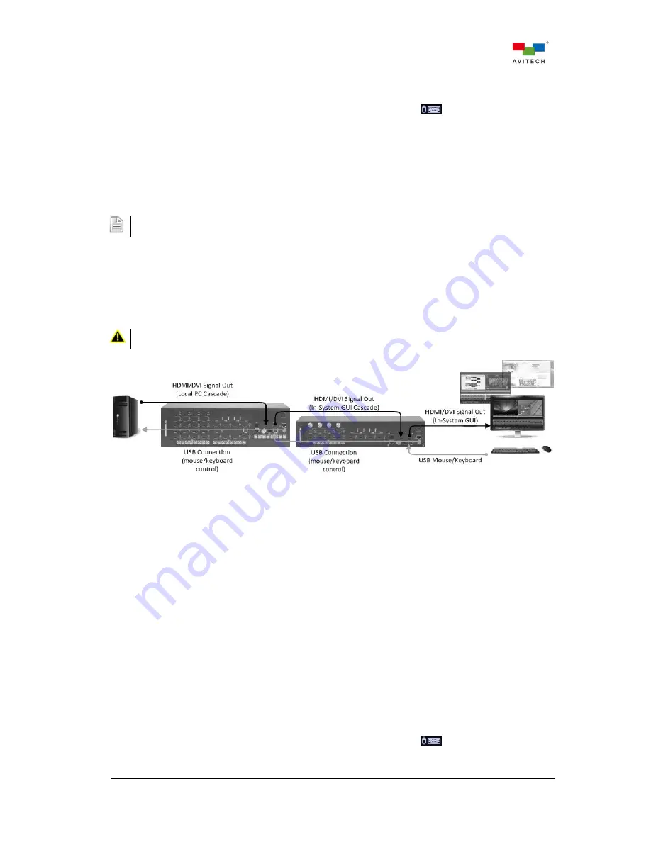
2.10 Basic Setup in Cascading
The following shows a typical setup with two Pacific MS modules in cascade with a local computer. This
allows user to freely access connected modules’ in-system GUI to control any Pacific MS as well as the
local computer from the same monitor, mouse, and keyboard console.
DO NOT place any object on the top or side panels of the Pacific MS.
Doing so could affect their internal components and/or heat dissipation.
Figure 2-20
Pacific MS in Cascade with a Local System Setup
Step 1. For setting up individual Pacific MS modules, follow step 1 – 4 as outlined in the previous
section (2.9) “Basic Setup for KVM Switching”.
Alternatively, follow step 1 – 2 as outlined in section (2.8) “Basic Setup for Video Switching and
Routing” if no mouse/keyboard functions we be needed.
Step 2. Connect the HDMI or DVI (through a DVI to HDMI adapter) output of the local computer to the
HDMI IN on the Pacific MS (2)’s control card.
Step 3. Connect a USB A/B cable to the local computer’s USB type A port, and connect the other end to
the USB type B port (PC) on the Pacific MS (2)’s control card.
Step 4. Connect the HDMI OUT on the Pacific MS (2)’s control card to the HDMI IN on the Pacific MS
(1)’s control card using the HDMI cable.
Step 5. Connect a USB A/B cable to the USB type A port on the Pacific MS (2)’s control card, and
connect the other end to the USB type B port (PC) on the Pacific MS (1)’s control card.
Step 6. Connect a HDMI or DVI (through a HDMI to DVI adapter) monitor to the HDMI OUT of the
Pacific MS (1)’ control card for in-system GUI display.
Step 7. Connect a set of mouse and keyboard to the USB type A ports
on the Pacific MS (1)’
control card for in-system GUI control.
Local Computer
MS (2)
MS (1)


