27
Step 2. Press the SOURCE button to initiate video switching/routing.
Step 3. Select the target source to be switched/routed by pressing the corresponding input button. The
pressed button will illuminate.
Step 4. Press the DESTINATION button to begin assigning destination(s) where the selected source
will be switched/routed.
Step 5. Select the target destination(s) by pressing the corresponding output button(s). Multiple
destinations can be selected for routing (the order of selection will not affect the routing result).
The pressed button(s) will illuminate; press the illuminated output button(s) to cancel the
assignment to the respective destination.
Depending on types of output cards, a video signal can be switched to display in full screen (SOB-H, SOB-T,
or SOB-HPW in Seamless mode), or switched to a window of a multiview display (SOB-QPW or SOB-HPW in
Dual mode).
Step 5. Press the TAKE button to confirm and execute the switching/routing operation.
Figure 3-3
FPB Control Sequence Diagram
Step 6. Verify the routing status on the FPB by pressing the target input or output button. Pressing an
input button will illuminate the button itself and all of the outputs that it is routed to. Likewise,
pressing an output button will illuminate the button itself, the input it is routed from, and all the
other outputs routed from the same input.
1. Switching or routing a source to the destination(s) in which the source has already been routed to will
cancel the original routing (only through FPB control).
2. The FPB is used to control video switching/routing (along with embedded audio and bundled
mouse/keyboard control). For separate mouse/keyboard routing configuration, use the Pacific MS’
in-system GU instead.
3. The FPB control will be automatically locked upon sensing an idle period of 30 seconds.
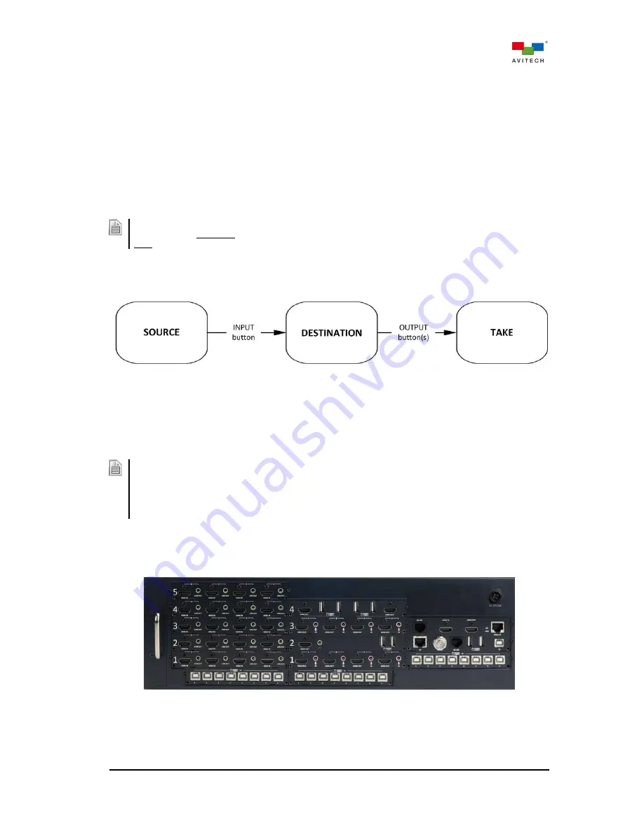
The following examples demonstrate video routing on the Pacific MS-3 using the FPB. The MS-3
chassis below includes five SIB-H input cards. Also installed in the chassis are one SOB-H, SOB-QPW,
SOB-H, and SOB-HPW output card in output card slot 1, 2, 3, and 4 respectively.
Figure 3-4
Pacific MS-3 Rear Panel for FPB Routing Demonstration


