Section 03
ENGINE
Subsection 05
(COOLING SYSTEM)
VMR2004_128_03_05A.FM
03-05-7
Installation
The installation is the opposite of the removal pro-
cedure.
CAUTION:
To prevent leaking, take care that
the gasket is exactly in groove when you rein-
stall the water pump housing.
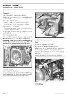
Tightening sequence for screws on water pump
housing is as per following illustration (criss-cross).
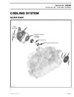
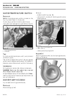
WATER PUMP IMPELLER
Removal
Remove:
– water pump housing
no. 3
– impeller
no. 4
.
1. Impeller
CAUTION:
Water pump shaft
no. 5
and impeller
no. 4
have right-hand threads. Remove by turn-
ing counterclockwise and install by turning
clockwise.
Inspection
Check impeller for cracks or other damage. Replace
impeller if damaged.
Installation
The installation is the opposite of the removal pro-
cedure. Pay attention to the following detail.
CAUTION:
Be careful not to damage impeller
wings during installation.
WATER PUMP SHAFT
Removal
Remove:
– water pump housing
no. 3
– impeller
no. 4
– magneto housing cover
(refer to
MAGNETO SYSTEM)
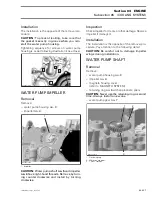
– retaining ring
no. 6
with appropriate pliers
CAUTION:
Never use the retaining ring a second
time. Always install a new one.
– water pump gear
no. 7
1. Retaining ring
2. Water pump gear
3. Thrust washer
4
R400motr231B
2
3
1
1
R400motr140A
3
1
R400motr141A
2
Содержание M-50 x 4
Страница 1: ...1 AUSA M 50 x 4 ROTAX ENGINE WORKSHOP MANUAL ...
Страница 2: ......
Страница 3: ......
Страница 7: ......
Страница 27: ......
Страница 31: ......
Страница 59: ......
Страница 85: ......
Страница 99: ......
Страница 136: ...Section 04 FUEL SYSTEM Subsection 03 CARBURETOR VMR2004_137_04_03A FM 04 03 1 CARBURETOR 0 V07F0ZS Harness assembly ...
Страница 147: ......
Страница 155: ......


