Section 03
ENGINE
Subsection 09
(CYLINDER AND HEAD)
VMR2004_132_03_09A.FM
03-09-15
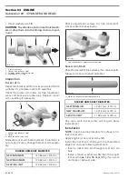
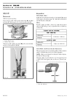
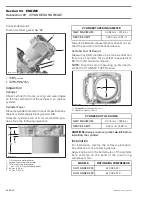
1. Valve spring compressor clamp (P/N 529 035 724)
2. Valve spring compressor cup (P/N 529 035 725)
3. Valve cotter
LOCATE VALVE SPRING COMPRESSOR CLAMP IN CENTER OF
THE VALVE
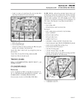
Remove valve cotters
no. 34
.
Withdraw valve spring compressor, valve spring
retainer
no. 35
and valve spring
no. 33
.
Inspection
Check valve spring for visible damages. If so, replace
valve spring.
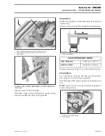
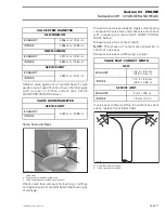
Check valve spring for free length and straightness.
A. Valve spring length
Replace valves springs if not within specifications.
Installation
For installation, reverse the removal procedure.
Pay attention to the following details.
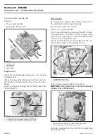
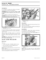
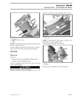
Colored area of the valve spring must be placed on
top.
NOTE:
Valve cotter must be properly engaged in
valve stem grooves.
1. Position of the valve spring
2. Valve cotters
1
R400motr78A
3
2
R400motr79A
VALVE SPRING FREE LENGTH
NEW NOMINAL
40.81 mm (1.607 in)
SERVICE LIMIT
39.00 mm (1.535 in)
R400motr80A
A
2
R400motr81A
1
Содержание M-50 x 4
Страница 1: ...1 AUSA M 50 x 4 ROTAX ENGINE WORKSHOP MANUAL ...
Страница 2: ......
Страница 3: ......
Страница 7: ......
Страница 27: ......
Страница 31: ......
Страница 59: ......
Страница 85: ......
Страница 99: ......
Страница 136: ...Section 04 FUEL SYSTEM Subsection 03 CARBURETOR VMR2004_137_04_03A FM 04 03 1 CARBURETOR 0 V07F0ZS Harness assembly ...
Страница 147: ......
Страница 155: ......


