Section 03
ENGINE
Subsection 10
(CRANKSHAFT/BALANCER SHAFT)
VMR2004_133_03_10A.FM
03-10-13
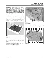
CAUTION:
Failure to strictly follow this proce-
dure may cause screw to loosen and lead to
engine damage. The bushing tapered end must
be against the counterweight. Besides, as the
“crankpin” screw has been stretched from the
previous installation, it is very important to
use
a new screw at assembly
.
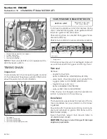
1. Angle torque wrench
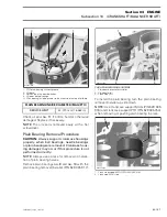
1. Insertion of balancer shaft
Align the marks of crankshaft and balancer shaft.
1. Punched marks located in the gears
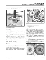
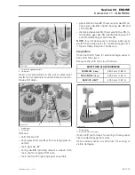
After reinstalling of crankcase MAG, measure axial
clearance of crankshaft with a feeler gauge on the
PTO side between PTO crankcase and crankshaft
thrust surface.
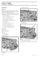
CAUTION:
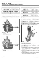
Install crankshaft locking bolt (P/N 529
035 617) right away to put crankshaft in TDC
position before installing the camshaft and
rockers (refer to CYLINDER AND HEAD).
1. Crankshaft locking bolt (P/N 529 035 617)
2. Engagement groove for TDC position of the piston
NOTE:
Always degrease tapers on both sides of
the crankshaft before reinstalling rotor or CVT.
CAUTION:
Make sure the woodruff key on crank-
shaft MAG is present and correctly in place.
1
R400motr37A
1
R400motr38A
1
R400motr25A
2
R400motr39A
1
Содержание M-50 x 4
Страница 1: ...1 AUSA M 50 x 4 ROTAX ENGINE WORKSHOP MANUAL ...
Страница 2: ......
Страница 3: ......
Страница 7: ......
Страница 27: ......
Страница 31: ......
Страница 59: ......
Страница 85: ......
Страница 99: ......
Страница 136: ...Section 04 FUEL SYSTEM Subsection 03 CARBURETOR VMR2004_137_04_03A FM 04 03 1 CARBURETOR 0 V07F0ZS Harness assembly ...
Страница 147: ......
Страница 155: ......


