Section 03
ENGINE
Subsection 11
(GEARBOX)
03-11-16
VMR2004_134_03_11A.FM
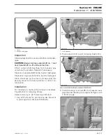
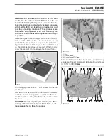
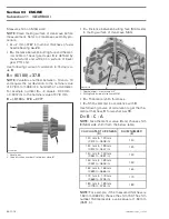
Insert a flat screwdriver in the slot of index lever
no. 8
. Turn screwdriver counterclockwise and in-
stall shift drum on park position as per the follow-
ing illustration.
1. Park position (flat area on index washer)
2. Index lever
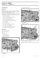
Insert shift shaft
no. 6
with mark in line to first tooth
on shift drum.
1. Mark on shift shaft
2. First tooth on shift drum
Install parking lever
no. 7
.
Bevel Gear Adjustment
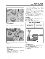
Use following course of calculation to adjust bevel
gear in place between crankcase PTO and MAG.
NOTE:
Only necessary if the output shaft axial
clearance of the bevel gear is out of specification.
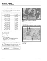
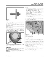
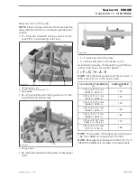
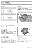
Measure following items and enter measurement
in the following list:
1
R400trans22A
2
1
R400trans23A
2
LETTER
MEASUREMENT 1
MEASUREMENT 2
A
2 mm (.0787 in)
2 mm (.0787 in)
B
C
D
E
F
G
H
I
J
Содержание M-50 x 4
Страница 1: ...1 AUSA M 50 x 4 ROTAX ENGINE WORKSHOP MANUAL ...
Страница 2: ......
Страница 3: ......
Страница 7: ......
Страница 27: ......
Страница 31: ......
Страница 59: ......
Страница 85: ......
Страница 99: ......
Страница 136: ...Section 04 FUEL SYSTEM Subsection 03 CARBURETOR VMR2004_137_04_03A FM 04 03 1 CARBURETOR 0 V07F0ZS Harness assembly ...
Страница 147: ......
Страница 155: ......

