Section 03
ENGINE
Subsection 09
(CYLINDER AND HEAD)
VMR2004_132_03_09A.FM
03-09-13
CAMSHAFT
Removal
The camshaft can be removed with the cylinder
head installed.
Remove:
– valve cover (see VALVE COVER
above)
– chain tensioner (see CHAIN TENSIONER above)
– camshaft timing gear
(see CAMSHAFT TIMING GEAR above)
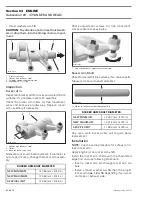
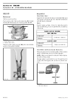
– camshaft retaining plate
no. 26
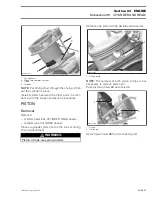
1. Cylinder head
2. Allen screws
3. Camshaft retaining plate
– rocker arms (see ROCKER ARM
above)
– camshaft
no. 32
.
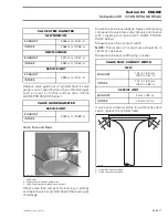
NOTE:
Rotate camshaft so that intake/exhaust
lobe shows to upper side of cylinder head to ease
removal of the camshaft.
1. Area for camshaft lobes
2. Camshaft
3. Camshaft retaining plate
Inspection
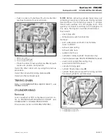
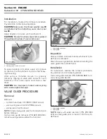
Check each lobe and bearing journal of camshaft
for scoring, scuffing, cracks or other signs of wear.
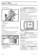
Measure camshaft bearing journal diameter and
lobe height using a micrometer.
A. Camshaft lobe (exhaust valves)
B. Camshaft lobe (intake valves)
C. Camshaft bearing journal MAG side
D. Camshaft bearing journal PTO side
1
R400motr65A
2
3
R400motr75A
1
3
2
CAMSHAFT LOBE — EXHAUST VALVES
NEW MINIMUM
32.027 mm (1.2609 in)
NEW MAXIMUM
32.047 mm (1.2617 in)
SERVICE LIMIT
32.000 mm (1.2598 in)
CAMSHAFT LOBE — INTAKE VALVES
NEW MINIMUM
32.343 mm (1.2733 in)
NEW MAXIMUM
32.363 mm (1.2741 in)
SERVICE LIMIT
32.300 mm (1.2717 in)
CAMSHAFT BEARING JOURNAL — MAG SIDE
NEW MINIMUM
34.959 mm (1.3763 in)
NEW MAXIMUM
34.975 mm (1.3770 in)
SERVICE LIMIT
34.950 mm (1.3760 in)
CAMSHAFT BEARING JOURNAL — PTO SIDE
NEW MINIMUM
21.959 mm (.8645 in)
NEW MAXIMUM
21.980 mm (.8654 in)
SERVICE LIMIT
21.950 mm (.8642 in)
C
R400motr76A
A
B
D
Содержание M-50 x 4
Страница 1: ...1 AUSA M 50 x 4 ROTAX ENGINE WORKSHOP MANUAL ...
Страница 2: ......
Страница 3: ......
Страница 7: ......
Страница 27: ......
Страница 31: ......
Страница 59: ......
Страница 85: ......
Страница 99: ......
Страница 136: ...Section 04 FUEL SYSTEM Subsection 03 CARBURETOR VMR2004_137_04_03A FM 04 03 1 CARBURETOR 0 V07F0ZS Harness assembly ...
Страница 147: ......
Страница 155: ......


