Section 03
ENGINE
Subsection 11
(GEARBOX)
VMR2004_134_03_11A.FM
03-11-13
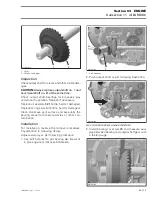
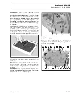
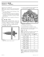
1. Shift fork engagement pin
2. Shift drum
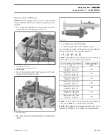
Insert a flat screwdriver in the slot of index lever
no. 8
. Turn screwdriver counterclockwise and re-
move shift drum.
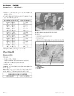
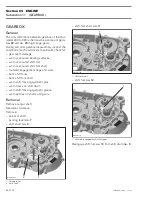
1. Index lever
2. Shift drum
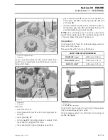
Remove:
– shift fork
no. 13
– bevel gear shaft
no. 21
with low range gear as-
sembly
– main gear
no. 27
– O-ring
no. 28
including distance sleeve from
main shaft on engine PTO side
– main shaft with high range gear assembly
– gear selection
no. 22
, thrust washer
no. 23
, re-
verse gear
no. 25
, needle bearing
no. 24
and
shim
no. 26
– distance sleeve
no. 14
, thrust washer
no. 15
, in-
termediate gear
no. 16
, needle bearing
no. 17
and intermediate gear shaft
no. 18
.
NOTE:
It is not necessary to remove index lever
no. 8
. Check index lever for visible damage and if
it moves freely. Replace if necessary.
Inspection
Check both shift forks for visible damage, wear or
bent shift fork claws.
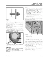
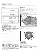
Measure the shift fork claw thickness.
1. Micrometer
A. Shift fork claw thickness
Check shift drum tracks for scoring or heavy wear
like rounded engagement slots.
Check index washer on shift drum for scoring or
visible damages.
1
R400motr208A
2
1
R400trans18A
2
SHIFT FORK CLAW THICKNESS
MINIMUM (new)
4.800 mm (.189 in)
MAXIMUM (new)
4.900 mm (.193 in)
SERVICE LIMIT
4.750 mm (.187 in)
1
R400trans19A
A
Содержание M-50 x 4
Страница 1: ...1 AUSA M 50 x 4 ROTAX ENGINE WORKSHOP MANUAL ...
Страница 2: ......
Страница 3: ......
Страница 7: ......
Страница 27: ......
Страница 31: ......
Страница 59: ......
Страница 85: ......
Страница 99: ......
Страница 136: ...Section 04 FUEL SYSTEM Subsection 03 CARBURETOR VMR2004_137_04_03A FM 04 03 1 CARBURETOR 0 V07F0ZS Harness assembly ...
Страница 147: ......
Страница 155: ......


