Section 04
FUEL SYSTEM
Subsection 03
(CARBURETOR)
04-03-2
VMR2004_137_04_03A.FM
GENERAL
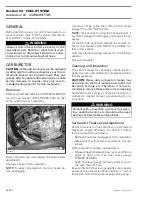
Before performing any job on the fuel system, al-
ways turn fuel valve to OFF position and discon-
nect BLACK (-) cable from battery.
CARBURETOR
CAUTION:
Although some jets can be replaced
by other jets from other carburetors, such mod-
ifications should not be performed. They can
greatly affect engine calibration and can cause
severe damage to engine. Use only recom-
mended jetting specific for this carburetor.
Removal
Remove air filter box (refer to AIR INTAKE SILENCER).
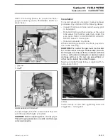
Install hose pincher (P/N 295 000 076) on fuel
pump outlet hose at carburetor.
Drain carburetor by unscrewing the drain screw
underneath.
Unplug all hoses from carburetor.
NOTE:
To ease reinstallation, mark all hoses be-
fore unplugging.
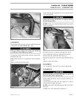
Unscrew choke cable then remove the choke
plunger from the throttle body.
NOTE:
Take care not to drop the choke plunger. If
so, check plunger for damages and replace if nec-
essary.
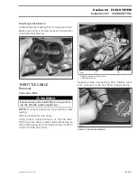
On the RH side of vehicle, remove the throttle ca-
ble from carburetor. See THROTTLE CABLE fur-
ther in this section.
Unscrew clamp retaining carburetor to the intake
adaptor.
Pull out carburetor.
Cleaning and Inspection
The entire carburetor should be cleaned with a
general solvent and dried with compressed air be-
fore disassembly.
CAUTION:
Heavy duty carburetor cleaner may
be harmful to the float material and to the rub-
ber parts, O-rings, etc. Therefore, it is recom-
mended to remove those parts prior to cleaning.
Carburetor body and jets should be cleaned in a
carburetor cleaner following manufacturer’s in-
structions.
Carburetor Float Level Adjustment
Correct fuel level in float chamber is vital toward
maximum engine efficiency. To check for correct
float level proceed as follows:
– Remove float bowl and gasket from carburetor.
– Make sure that float arm is symmetric, not dis-
torted.
With carburetor chamber upside down:
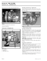
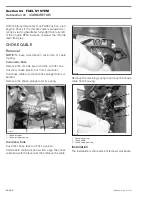
– Measure height between bowl seat and the top
edge of float arm. Use float level gauge
(P/N 529 035 520).
– Keep float level gauge perfectly vertical and in
line with main jet hole.
Ensure that both float level gauge tips are properly
positioned on carburetor body and that “L” arm is
leaning on float while compressing valve spring.
WARNING
Always disconnect battery exactly in the
specified order, BLACK (-) cable first. It is rec-
ommended to disconnect electrical connec-
tions prior to disconnecting fuel lines.
V07F05A
WARNING
Solvent with a low flash point such as gaso-
line, naphtha, benzol, etc., should not be used
as they are flammable and explosive.
Содержание M-50 x 4
Страница 1: ...1 AUSA M 50 x 4 ROTAX ENGINE WORKSHOP MANUAL ...
Страница 2: ......
Страница 3: ......
Страница 7: ......
Страница 27: ......
Страница 31: ......
Страница 59: ......
Страница 85: ......
Страница 99: ......
Страница 136: ...Section 04 FUEL SYSTEM Subsection 03 CARBURETOR VMR2004_137_04_03A FM 04 03 1 CARBURETOR 0 V07F0ZS Harness assembly ...
Страница 147: ......
Страница 155: ......


