TROUBLESHOOTING
Page 54
MVS User Manual
710-13019-00A
The MVS provides extensive information to help the operator diagnose and remedy any operating difficulties.
In addition to the motor and load protection features already described, the MVS reports in detail on the starter's own
state. Any internal failure will cause the soft starter to trip, and full details will be recorded in the trip log and event log.
10.1
Protection Responses
When a protection condition is detected, the MVS will write this to the event log and may also trip or issue a warning.
The soft starter's response to some protections may depend on the Protection Action settings (parameter group 16).
Some protection responses cannot be adjusted by the user. These trips are usually caused by external events (such as
phase loss) or by a fault within the soft starter. These trips do not have associated parameters and cannot be set to Warn
or Log.
If the MVS trips you will need to identify and clear the condition that triggered the trip, then reset the soft starter before
restarting. To reset a the starter, press the RESET button on the Controller or activate the Reset remote input.
If the MVS has issued a warning, the soft starter will reset itself once the cause of the warning has been resolved.
10.2
Trip Messages
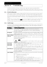
This table lists soft starter's protection mechanisms and the probable cause of the trip. Some of these can be adjusted using
parameter group 4
Protection Settings
and parameter group 16
Protection Action
, other settings are built-in system
protections and cannot be set or adjusted.
Error Message
Possible cause/Suggested solution
Assy Power Low
Control voltage to the power interface PCB has dropped below the required level.
Check that the control voltage transformer and control circuit fuses are healthy, and that voltage
is present at the terminal block (terminals A1-A2 or A2-A3) within the specified range.
This trip is not adjustable.
Battery/clock
A verification error has occurred on the real time clock, or the backup battery voltage is low. If the
battery is low and the power is off, date/time settings will be lost. Reprogram the date and time.
Related parameters: 16M
Bypass fail (bypass
contactor)
The bypass contactor has welded closed or is not operating correctly. There may be a problem
with the control circuit or the contactor coil.
Check the condition of the bypass contactor's main poles. Check the operation of the contactor
control circuitry and contactor coil.
This trip is not adjustable.
NOTE
You can use the Run Simulation to check the bypass contactor's operation without
mains voltage connected.
Cond 1 Invalid
Cond 2 Invalid
Cond 3 Invalid
There is a problem with the SCR firing or feedback system.
Check that the fibre-optic cables between the power interface PCB and the gate drive
adaptor PCBs are properly connected.
The value of the grading resistor may not be suitable for the nominal mains voltage. If you
are using a low voltage motor for testing purposes, contact your local supplier for advice.
This trip is not adjustable.
Control Volts Low
Control voltage to the Controller has dropped below the required level.
Check that the control voltage transformer and control circuit fuses are healthy, and that voltage
is present at terminals A11, A12 within the specified range.
This trip is not adjustable.
Current imbalance
Current imbalance can be caused by problems with the motor, the environment or the installation,
such as:
An imbalance in the incoming mains voltage
A problem with the motor windings
A light load on the motor
A phase loss on input terminals L1, L2 or L3 during Run mode
An SCR that has failed open circuit. A failed SCR can only be definitely diagnosed by
replacing the SCR and checking the starter's performance.
If you have recently replaced or repaired a phase arm, the connector at the back of the phase arm
may not be securely plugged into the connector on the body of the power assembly.
Section 10
Troubleshooting
Содержание MVS
Страница 1: ......
Страница 67: ...APPENDIX Page 66 MVS User Manual 710 13019 00A ...
Страница 68: ...APPENDIX 710 13019 00A MVS User Manual Page 67 ...
Страница 69: ...APPENDIX Page 68 MVS User Manual 710 13019 00A ...
Страница 70: ...È710 13019 00A ËÍ 7 1 0 1 3 0 1 9 0 0 A ...


