INSTALLATION
Page 18
MVS User Manual
710-13019-00A
4.9
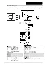
Internal Wiring
KM1 Main
contactor
A3
Power interface PCB
KM2 Bypass
contactor
(external)
3 Bypass
feedback
KM3
PFC contactor (optional)
4 Main
contactor
output
1 COM.
Connect
to:
5 Bypass
contactor
output
A2-1(1) for 110 or 220 VAC coil
6
Run (PFC) output
A2-2(1) for 120 or 230 VAC coil
7 Power
supply
A2-3(1) for 130 or 240 VAC coil
A4
Controller
A2
Control voltage terminal block
8
Fibre optic cables (supplied, but must be connected at
site)
2
Feed connected to A1 or A3 must be
externally fused.
A5
Gate drive PCBs
NOTE
The control voltage terminal section (A2) has links fitted for 110 VAC external control and contactor coil
voltages. For other voltages, remove these links and refit as indicated.
External control supply
Contactor coil supply (KM1 - KM3)
Voltage Connect
into
Link
from Voltage
Link
from
110 VAC
A2(2) to A2-1(2)
110 VAC
120 VAC
A1 and A2
A2(2) to A2-2(2)
120 VAC A1(2) to 13(2)
130 VAC
A2(2) to A2-3(2)
130 VAC
220 VAC
A2(2) to A2-1(2)
220 VAC
230 VAC
A3 and A2
A2(2) to A2-2(2)
230 VAC A3(2) to 13(2)
240 VAC
A2(2) to A2-3(2)
240 VAC
A4
A5
A3
A2
03221.F
1
2
3
4
5
6
Содержание MVS
Страница 1: ......
Страница 67: ...APPENDIX Page 66 MVS User Manual 710 13019 00A ...
Страница 68: ...APPENDIX 710 13019 00A MVS User Manual Page 67 ...
Страница 69: ...APPENDIX Page 68 MVS User Manual 710 13019 00A ...
Страница 70: ...È710 13019 00A ËÍ 7 1 0 1 3 0 1 9 0 0 A ...


