INSTALLATION
Page 12
MVS User Manual
710-13019-00A
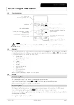
1
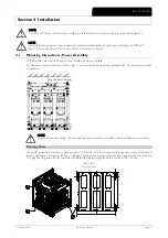
M10 bolts with belleville washers
2
M10 nut
3
M12 mounting holes
Model
A
mm (inch)
B
mm (inch)
C
mm (inch)
Torque
(phase arms)
Torque
(base)
MVSxxxx-V02 636
513
68.5
MVSxxxx-V03
(25.0)
(20.0)
(2.7)
28~30 Nm
40 Nm
MVSxxxx-V04
MVSxxxx-V06
842
663
68.5
28~30 Nm
40 Nm
MVSxxxx-V07 (33.1)
(26.1)
(2.7)
* For models MVSxxxx-V02 to MVSxxxx-V04, these dimensions apply up to 321 A. For the same models with current
ratings of 500 and 600 A, the MVSxxxx-V06 dimensions apply.
4.2
Mounting Instructions - Controller
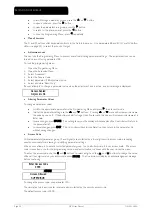
The Controller is secured into place using ten M4 nuts, affixed to the studs on the back of the controller.
To mount the controller, make a 186 mm x 300 mm cutout at the desired mounting location. Ensure adequate clearance
(>85 mm) is available behind the mounting location.If you intend to use a communication module, allow for a minimum
clearance of 120 mm behind the mounting panel.
Drill 5 mm holes to accommodate the studs on the controller. Fit the controller through the cutout and tighten the nuts
onto the studs.
NOTE
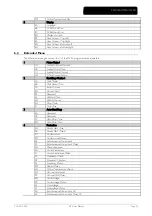
Before installation, always ensure that you are using the correct controller for the soft starter. This can
be checked by comparing the serial number on the back of the controller with the serial number on the
front of the power assembly.
1
Serial number
112 (4.41)
300 (11.81)
310 (12.20)
340 (13.39)
22
0
(8.
66
)
19
6
(7.
72
)
18
6
(7.
32
)
80.0 (3.15)
0326
3.
B
MAIN CONTROL MODULE
MVS-0321-V04-C12
S/N: 197803-459
MVS 0321-V04-C12
O/C: MVS 0321-411 S/N: 197803-459
INPUT RATING:
4160 VAC 50/60 Hz
OUTPU T RATING:
321 A : AC53b 4-20 1780
AUXILIARY CONTACTS:
8A, 30 VDC resistive / 10 A, 250 VAC 360 VA
WITHSTAND CURRENT:
20 kA
WITHSTAND VOLTAGE:
45000 VAC Cat III
AUXILIARY CONTACTS:
#24-#14 AWG, 0.2-2.5 mm2 (0.5 NM, 4.4 lb-in)
AUCOM
IND. CONT. EQ.
32 AN
Z79
IND. CONT. EQ.
32 AN
Z79
1
03
530.
E
Содержание MVS
Страница 1: ......
Страница 67: ...APPENDIX Page 66 MVS User Manual 710 13019 00A ...
Страница 68: ...APPENDIX 710 13019 00A MVS User Manual Page 67 ...
Страница 69: ...APPENDIX Page 68 MVS User Manual 710 13019 00A ...
Страница 70: ...È710 13019 00A ËÍ 7 1 0 1 3 0 1 9 0 0 A ...


