SAFETY AND MAINTENANCE MANUAL
1NO0055UK-00
PIAF 10
E
71
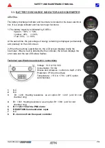
1. Plug the charger on the power socket.
2. The RED Led indicates the start of the charging cycle.
3. The YELLOW Led indicates the battery is 80% charged.
4. The GREEN Led indicates the battery is 100% charged.
5. At the end of the charge, the charger plug must be disconnected.
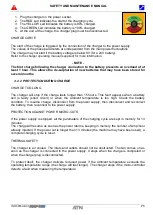
CHARGE CURVE
The start of the charge is triggered by the connection of the charger to the power supply.
The values of the phase parameters are independent from the main power fluctuations.
The charge may not start if the battery voltage is below 9V (for a 24V battery).
Refer to the charger operating manual (supplied) for more information.
- NOTE -
The first charge following the charger connection to the battery presents an overload of at
least 1 hour. This allows the de-sulphation of new batteries that may have been stored for
several months.
3.2.2 PROTECTION DURING CHARGE
CHARGE TOO LONG
The charger will stop if the charge lasts longer than 15 hours. This fault appears when a battery
cell is faulty (short circuit) or when the ambient temperature is too high. Check the battery
condition. To resume charge, disconnect from the power supply, then disconnect and reconnect
the battery, then reconnect to the power supply.
PROTECTION AGAINST POWER MICRO-CUTS
If the power supply is stopped, all the parameters of the charging cycle are kept in memory for 13
minutes.
The charge will resume as soon as the power returns, keeping in memory the number of Amp/hour
already injected. If the power cut is longer than 13 minutes (the machine may have been used), a
complete charging cycle is reset.
THERMAL SAFETY
The charger is air cooled. The inlets and outlets should not be obstructed. The fan comes on as
soon as the charger is connected to the power supply. It stops when the charge is completed or
when the charger plug is disconnected.
To protect itself, the charger delivers reduced power if the ambient temperature exceeds the
operating temperature range (the charge will last longer). The charger stops if the micro-controller
detects a fault when measuring the temperature.
Содержание PIAF 10E 2018
Страница 2: ...SAFETY AND MAINTENANCE MANUAL 1NO0055UK 00 PIAF 10E 2 DISTRIBUTOR STAMP...
Страница 8: ...SAFETY AND MAINTENANCE MANUAL 1NO0055UK 00 PIAF 10E 8...
Страница 10: ...SAFETY AND MAINTENANCE MANUAL 1NO0055UK 00 PIAF 10E 10...
Страница 13: ...SAFETY AND MAINTENANCE MANUAL 1NO0055UK 00 PIAF 10E 13 Chapter I OPERATION AND SAFETY...
Страница 14: ...SAFETY AND MAINTENANCE MANUAL 1NO0055UK 00 PIAF 10E 14...
Страница 18: ...SAFETY AND MAINTENANCE MANUAL 1NO0055UK 00 PIAF 10E 18...
Страница 24: ...SAFETY AND MAINTENANCE MANUAL 1NO0055UK 00 PIAF 10E 24...
Страница 42: ...SAFETY AND MAINTENANCE MANUAL 1NO0055UK 00 PIAF 10E 42...
Страница 43: ...SAFETY AND MAINTENANCE MANUAL 1NO0055UK 00 PIAF 10E 43 Chapter II MAINTENANCE...
Страница 44: ...SAFETY AND MAINTENANCE MANUAL 1NO0055UK 00 PIAF 10E 44...
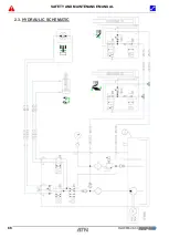
Страница 66: ...SAFETY AND MAINTENANCE MANUAL 1NO0055UK 00 PIAF 10E 66 2 3 HYDRAULIC SCHEMATIC...
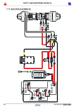
Страница 78: ...SAFETY AND MAINTENANCE MANUAL 1NO0055UK 00 PIAF 10E 78 3 10 ELECTRIC SCHEMATIC...
Страница 79: ...SAFETY AND MAINTENANCE MANUAL 1NO0055UK 00 PIAF 10E 79...
Страница 80: ...SAFETY AND MAINTENANCE MANUAL 1NO0055UK 00 PIAF 10E 80 NOTES...
Страница 81: ...SAFETY AND MAINTENANCE MANUAL 1NO0055UK 00 PIAF 10E 81 NOTES...

